Supercharge Your Innovation With Domain-Expert AI Agents!

Inkjet printhead with droplet stem anchor

a technology of droplet stem and droplet, which is applied in the field of microelectromechanical system (mems) devices, can solve problems such as drop misdirection

Active Publication Date: 2008-11-04
MEMJET TECH LTD +1
View PDF15 Cites 26 Cited by
  • Summary
  • Abstract
  • Description
  • Claims
  • Application Information

AI Technical Summary

Benefits of technology

This solution effectively minimizes drop misdirection, improving print quality by ensuring consistent and controlled ink drop trajectories across all nozzles, enhancing the precision and efficiency of inkjet printing.

Problems solved by technology

The droplet stem that attaches the ejected ink to the ink in the chamber immediately prior to drop separation, can be a cause of drop misdirection.

Method used


Image

  • Inkjet printhead with droplet stem anchor
  • Inkjet printhead with droplet stem anchor
  • Inkjet printhead with droplet stem anchor

Examples


Embodiment Construction

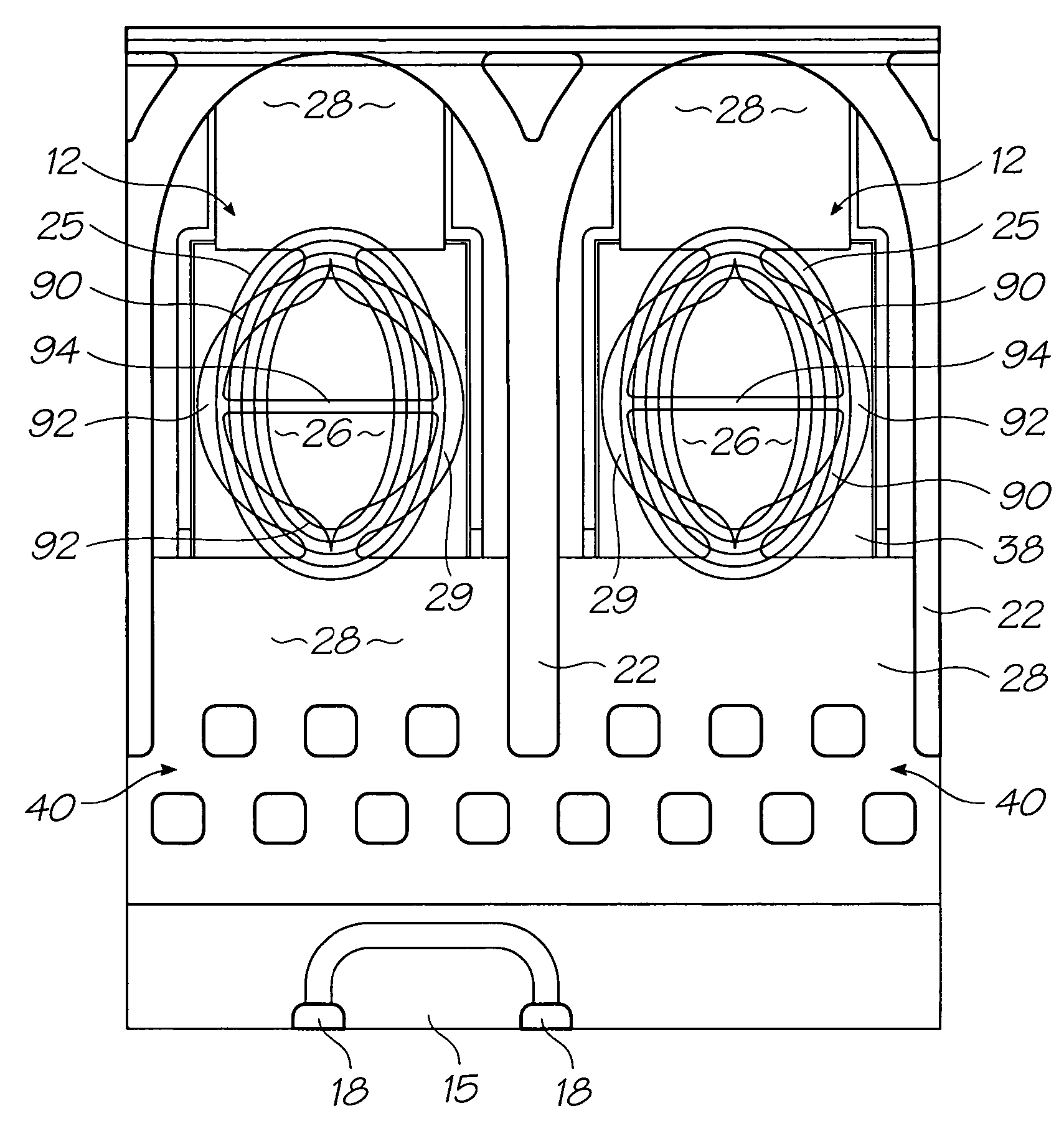
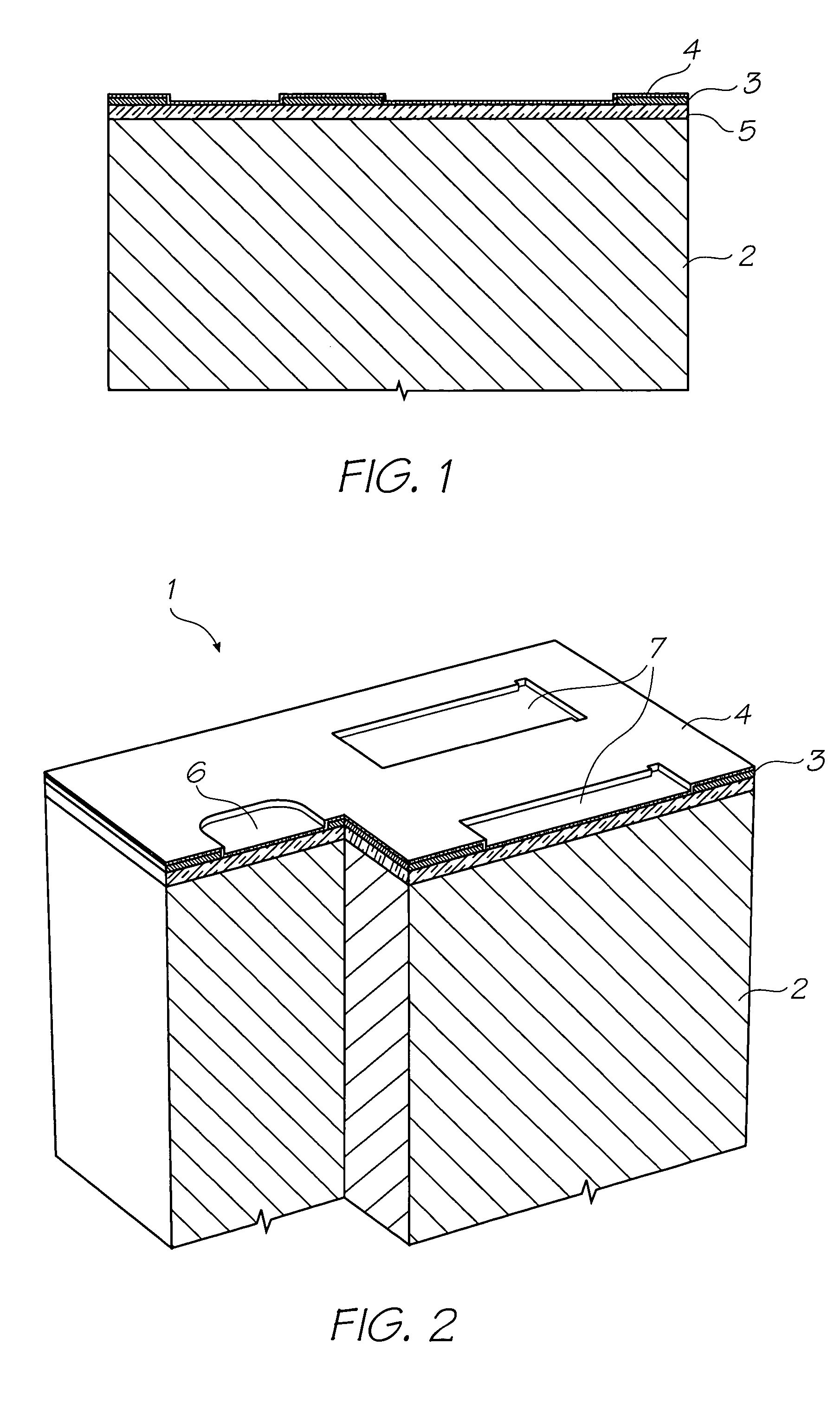
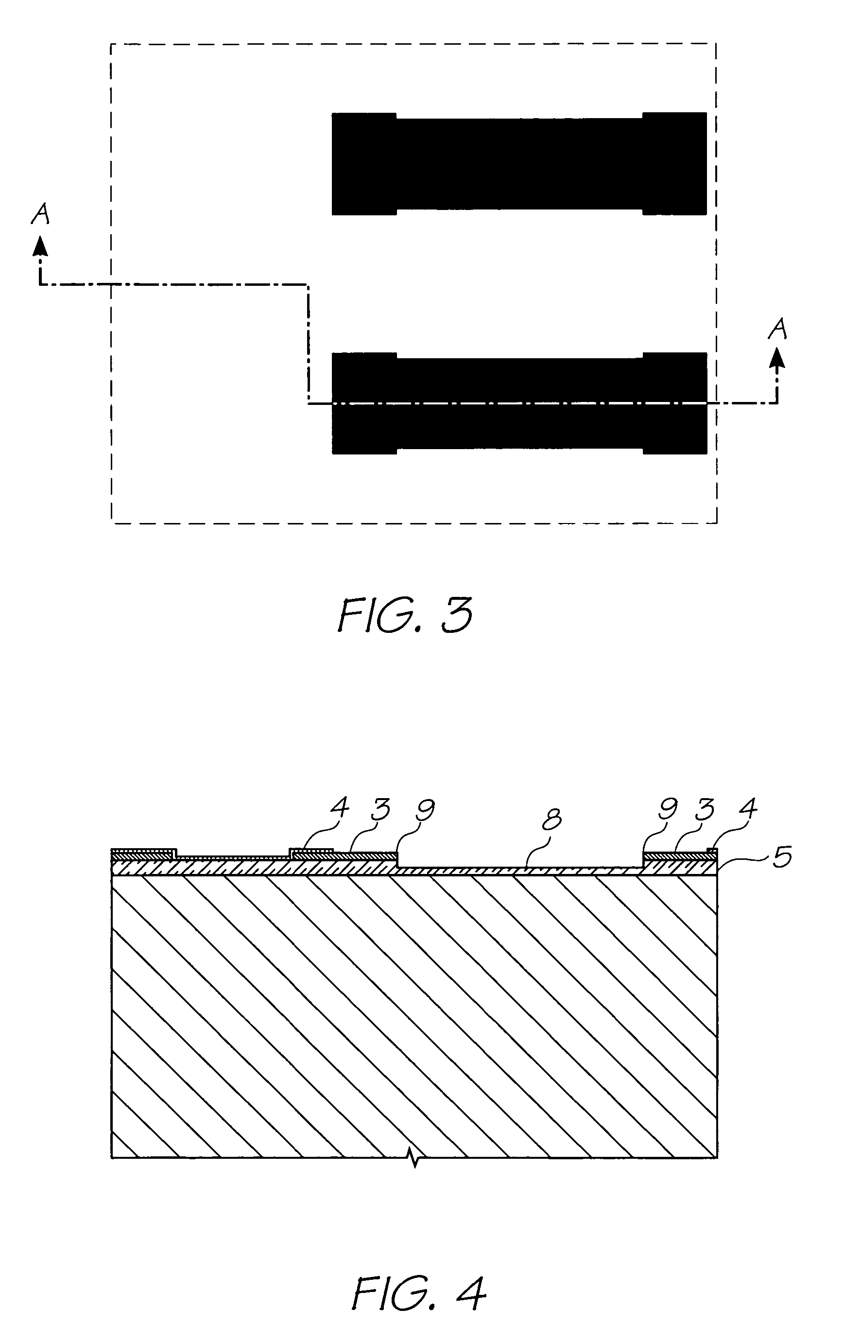
[0275]In the description than follows, corresponding reference numerals relate to corresponding parts. For convenience, the features indicated by each reference numeral are listed below.[0276]1. Nozzle Unit Cell[0277]2. Silicon Wafer[0278]3. Topmost Aluminium Metal Layer in the CMOS metal layers[0279]4. Passivation Layer[0280]5. CVD Oxide Layer[0281]6. Ink Inlet Opening in Topmost Aluminium Metal Layer 3.[0282]7. Pit Opening in Topmost Aluminium Metal Layer 3.[0283]8. Pit[0284]9. Electrodes[0285]10. SAC1 Photoresist Layer[0286]11. Heater Material (TiAlN)[0287]12. Thermal Actuator[0288]13. Photoresist Layer[0289]14. Ink Inlet Opening Etched Through Photo Resist Layer[0290]15. Ink Inlet Passage[0291]16. SAC2 Photoresist Layer[0292]17. Chamber Side Wall Openings[0293]18. Front Channel Priming Feature[0294]19. Barrier Formation at Ink Inlet[0295]20. Chamber Roof Layer[0296]21. Roof[0297]22. Sidewalls[0298]23. Ink Conduit[0299]24. Nozzle Chambers[0300]25. Elliptical Nozzle Rim[0301]25(a)...


PUM


Abstract

An inkjet printhead that has an array of ink chambers, each having a nozzle, a droplet stem anchor and an actuator for ejecting ink through the nozzle. During use, the ink ejected from the nozzle is attached to the droplet stem anchor by an ink stem until the stem breaks so that the ejected ink forms a separate drop.

Description

FIELD OF THE INVENTION[0001]The present invention relates to the field of micro-electromechanical systems (MEMS) devices and discloses an inkjet printing system MEMS techniques.CO-PENDING APPLICATIONS[0002]The following applications have been filed by the Applicant simultaneously with the present application:[0003]11 / 24667611 / 24667711 / 24667811 / 24667911 / 24668011 / 24668111 / 24671411 / 24671311 / 24668911 / 24667111 / 24667011 / 24666911 / 24670411 / 24671011 / 24668811 / 24671611 / 24671511 / 24670711 / 24670611 / 24670511 / 24670811 / 24669311 / 24669211 / 24669611 / 24669511 / 24669411 / 24668711 / 246718732268111 / 24668611 / 24670311 / 24669111 / 24671111 / 24669011 / 24671211 / 24671711 / 24670911 / 24670011 / 24670111 / 24670211 / 24666811 / 24669711 / 24669911 / 24667511 / 24667411 / 246667730393011 / 24667211 / 24667311 / 24668311 / 246682[0004]The disclosures of these co-pending applications are incorporated herein by reference.CROSS REFERENCES TO RELATED APPLICATIONS[0005]Various methods, systems and apparatus relating to the present invention are disclosed i...

Claims


Application Information

Patent Timeline
Patent Type & Authority Patents(United States)
IPC IPC(8): B41J2/05
CPCB41J2/1404B41J2/1603B41J2/1628B41J2/1631B41J2/1639B41J2/1642B41J2/1645B41J2002/14169B41J2002/14403B41J2002/14475B41J2202/11
Inventor WORSMAN, MATTHEW TAYLORAZIMI, MEHDISILVERBROOK, KIA
Owner MEMJET TECH LTD
Features
  • R&D
  • Intellectual Property
  • Life Sciences
  • Materials
  • Tech Scout
  • Unparalleled Data Quality
  • Higher Quality Content
  • 60% Fewer Hallucinations
Learn More