PWM/burst mode switching regulator with automatic mode change

a switching regulator and burst mode technology, applied in the direction of electric variable regulation, process and machine control, instruments, etc., can solve the problems of low power efficiency of pwm switchers, inability to anticipate the load current condition and make mode changes, and many such dual-mode switching regulators with separate pwm and non-pwm regulation loops. , to achieve the effect of reducing output impedance, fast response and high bandwidth

Inactive Publication Date: 2008-11-04
AVAGO TECH WIRELESS IP SINGAPORE PTE
View PDF5 Cites 18 Cited by
  • Summary
  • Abstract
  • Description
  • Claims
  • Application Information

AI Technical Summary

Benefits of technology

[0009]Accordingly, a switching regulator is provided that is able to achieve a fast response similar to a hysteretic self-oscillating switcher and at the same time able to precisely control its switching frequency similar to a PWM switcher. An added advantage that comes from the higher bandwidth is that lower output impedance for higher frequencies can be achieved, thus allowing smaller load capacitors to be used compared to conventional PWM switchers.
[0010]Automatic mode change of the switching regulator is also provided for improved efficiency while maintaining the same PWM regulation loop. Automatic transition from PWM to burst mode occurs based on load current condition without the need for any manual architecture change or external controller. When it is in burst mode, the behavior resembles the gated-oscillator topology.

Problems solved by technology

For low load currents, however, PWM switchers have low power efficiency due to the losses from high frequency switching.
However, for many applications, such as digital communications, it is not always possible to anticipate the load current condition and make mode changes for higher power efficiency.
As a result, many such dual-mode switching regulators with separate PWM and non-PWM regulation loops are inefficient.

Method used


Image

  • PWM/burst mode switching regulator with automatic mode change
  • PWM/burst mode switching regulator with automatic mode change
  • PWM/burst mode switching regulator with automatic mode change

Examples


Embodiment Construction

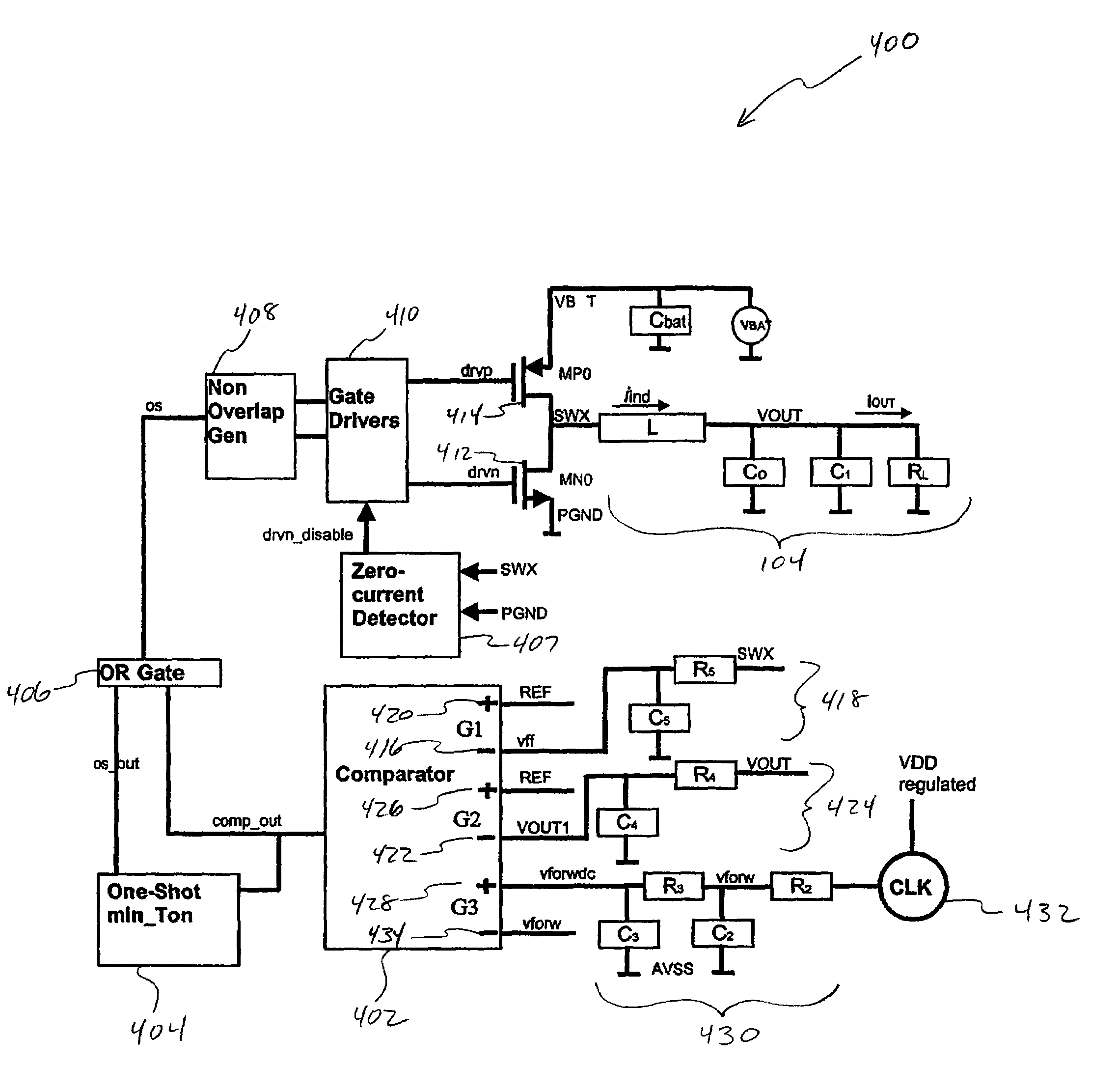
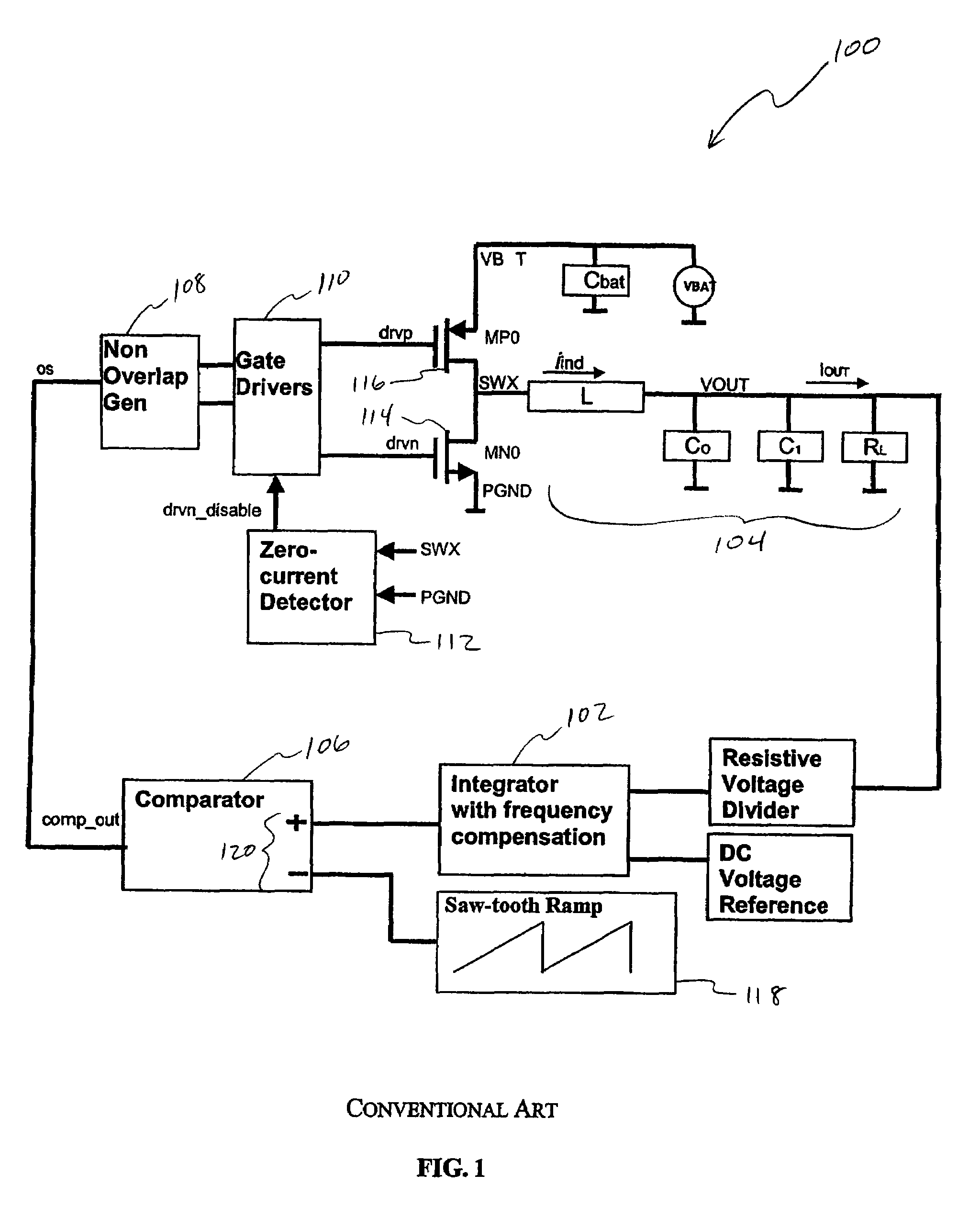
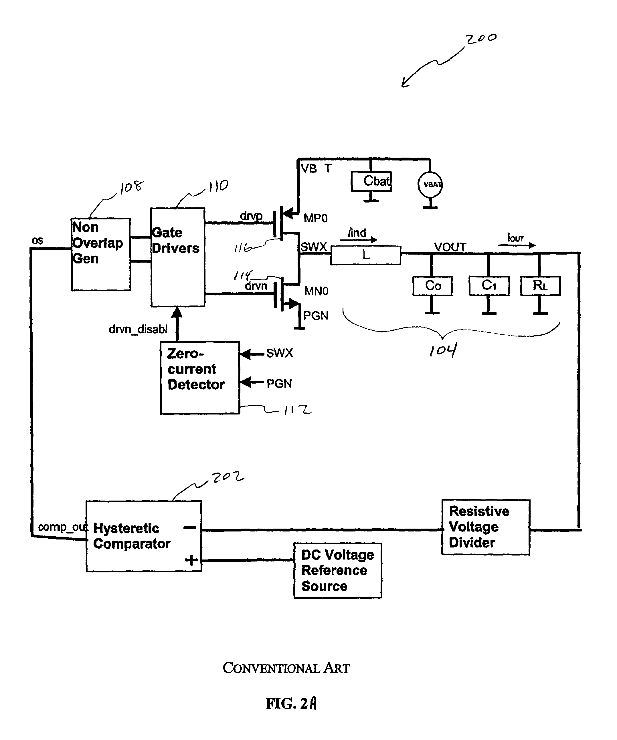
[0024]FIG. 1 illustrates a conventional pulse width modulation (“PWM”) type switcher 100. PWM switcher 100 includes an integrator 102, LC filter 104, single-input comparator 106, non-overlap generator 108, gate drivers 110, zero current detector 112, NMOS switch 114, and PMOS switch 116. NMOS switch 114 and PMOS switch 116 output a feedforward signal SWX to integrator 102 and zero current detector 112. Integrator 102 is in a feedback loop to provide a large low frequency gain for the feedback loop. Comparator 106 receives the output of integrator 102 and a saw-tooth reference ramp voltage 118 as differential input 120.

[0025]A side effect of having integrator 102 in the feedback loop followed by comparator 106 is that it slows down the loop response. This is because a change in output voltage VOUT caused by a sudden change in load current IOUT is significantly attenuated by integrator 102. This limits the range of instantaneous duty cycle adjustment that can be made by comparator 106...


PUM


Abstract

A switching regulator automatically operates in pulse width modulation (“PWM”) mode for high load currents and in burst mode for low load currents. The switching regulator includes a pair of switches to provide a regulated current to a load. The switching regulator further includes a multi-input comparator. A first input of the comparator is coupled to an output of the pair of switches. A second input of the comparator is coupled to a filtered version of the output and a third input is coupled to a reference waveform. The first, second and third inputs of the comparator form a combined input signal to the comparator. An output signal of the comparator is generated by comparing the combined input signal to a threshold of the comparator. The output signal determines a switching frequency of the pair of switches such that the switching frequency is automatically reduced when the load is decreased.

Description

CROSS REFERENCE TO RELATED APPLICATIONS[0001]The present application claims the benefit of U.S. Provisional Application No. 60 / 709,427, filed Aug. 19, 2005, which is hereby incorporated by reference in its entirety.BACKGROUND OF THE INVENTION[0002]1. Field of the Invention[0003]The present invention generally relates to the regulation of supply voltages by switching regulators. More specifically, the present invention provides a pulse width modulation and burst modes switching regulator having automatic mode change.[0004]2. Background Art[0005]Switching regulators are used to regulate supply voltages for powering circuits. Specifically, supply voltages are regulated down or regulated up to appropriate voltage levels by a switching regulator.[0006]Switching regulators can be broadly classified into fixed and non-fixed switching frequency types. Pulse width modulation (“PWM”) is typically used in the control loop for fixed frequency switchers. A high switching frequency is typically u...

Claims


Application Information

Patent Timeline
Patent Type & Authority Patents(United States)
IPC IPC(8): G05F1/575G05F1/618
CPCH02M3/1588H02M2001/0032Y02B70/1466Y02B70/16H02M1/0032Y02B70/10
Inventor LOW, KHIM LENGHO, DAVID SENG POHHSIAO, CHI-MINGCHAN, HUA BENG
Owner AVAGO TECH WIRELESS IP SINGAPORE PTE
Why Eureka
Try Eureka