Display device and driving method for a display device
- Summary
- Abstract
- Description
- Claims
- Application Information
AI Technical Summary
Benefits of technology
Problems solved by technology
Method used
Image

Examples
first embodiment
[0021]Description will now be given of embodiments by referring to a first embodiment and drawings associated therewith. In the drawings described below, the components having the same functions are assigned with the same reference numerals, and duplicated description thereof will be avoided. In the respective embodiments, the display device according to the present invention includes a liquid crystal display of normally black type by way of illustration. However, by modifying structure of pixels, the present invention is also applicable to a display device using electroluminescence of light-emitting elements such as a light-emitting diode. The present invention is also applicable to a liquid crystal display device of normally white type.
[0022]Next, the first embodiment will be described by referring to FIGS. 1 to 4.
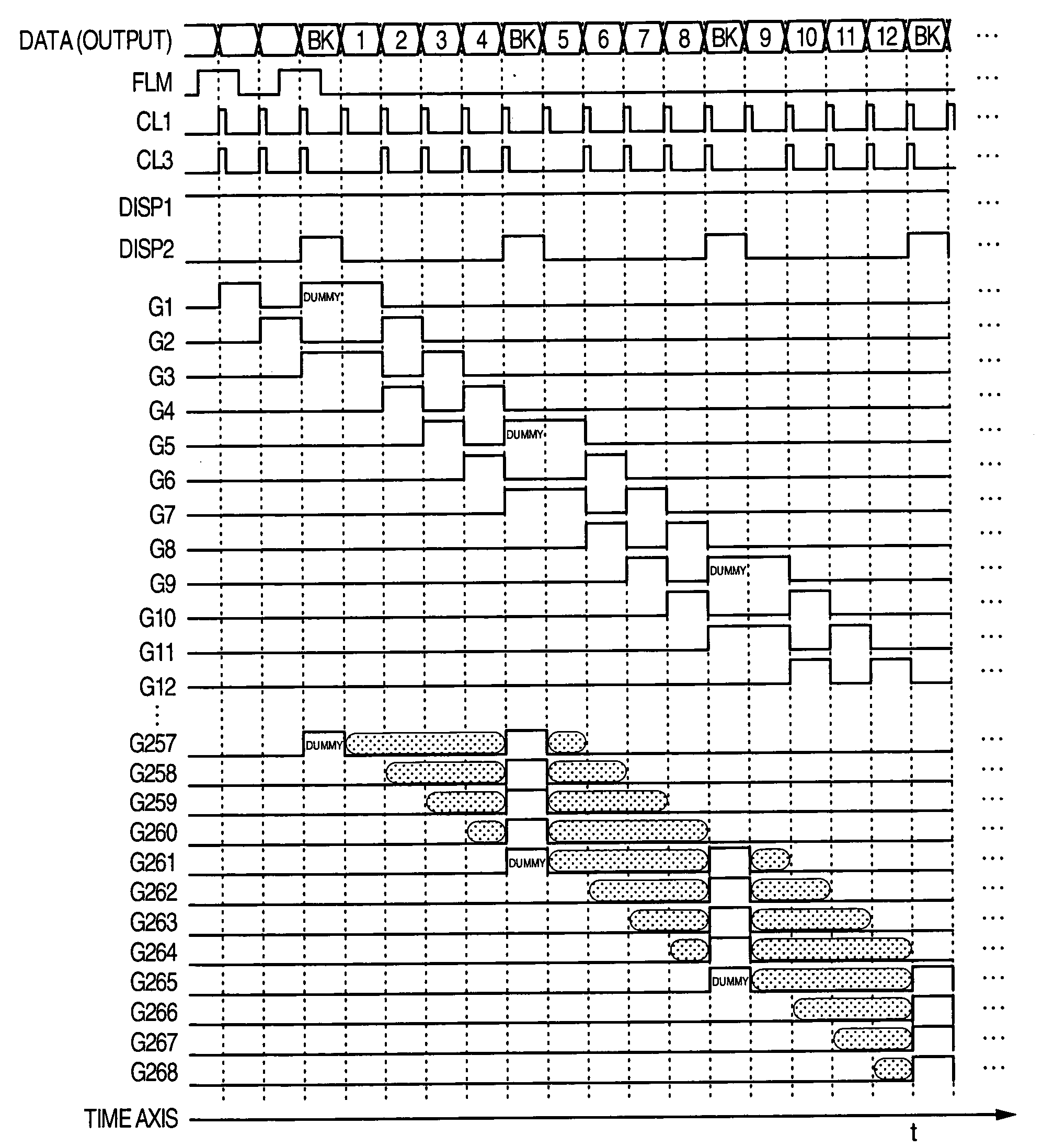
[0023]According to an aspect of the first embodiment, double gate driving is conducted in a liquid crystal display of active matrix type and blanking data insertion is d...
second embodiment
[0040]Next, a second embodiment will be described by referring to FIGS. 1, 2, and 5.
[0041]The liquid crystal display device of the second embodiment is almost the same as that of FIG. 1 and hence description of the video display principle of the display device will be avoided. The block diagram of a control circuit of the LC display device of the second embodiment is substantially the same as that of FIG. 2 and hence detailed description thereof will be avoided.
[0042]According to an aspect of the second embodiment, double gate driving is conducted also for the blanking data for which single gate driving is conducted in the first embodiment. Thanks to the driving method of the second embodiment, there can be obtained the advantage of the first embodiment and an advantage of improving the mobile picture blur inherent to a display device using the hold-type luminance response.
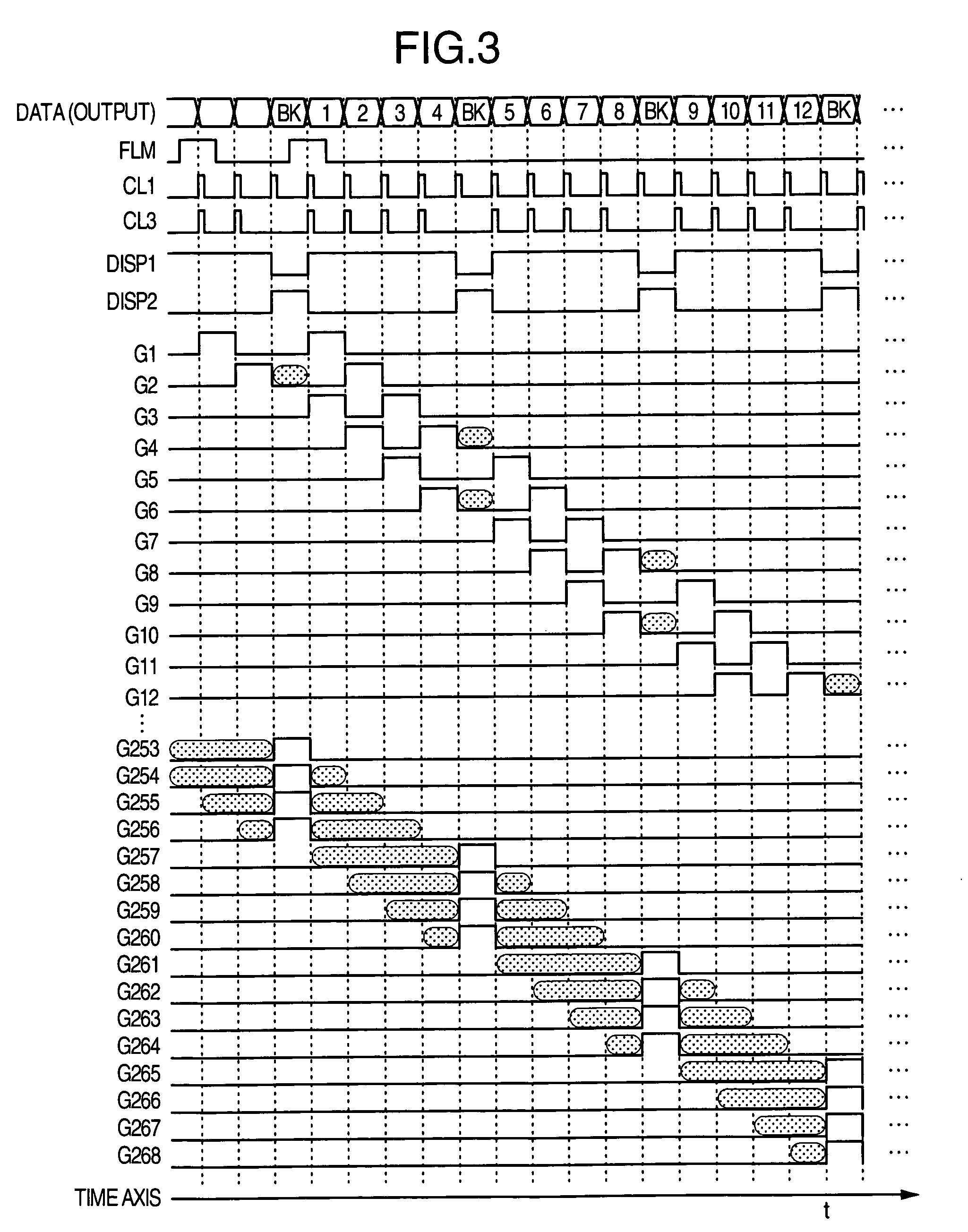
[0043]FIG. 5 is a timing chart showing waveforms of input signals to and output signals from the LC display con...
third embodiment
[0049]Next, a third embodiment will be described by referring to FIGS. 1, 2, 6, 7, and 8.
[0050]Since the liquid crystal display device of the third embodiment is almost the same as that of FIG. 1, description of the video display principle of the display device will be avoided. Similarly, the block diagram of a control circuit of the LC display device of the third embodiment is almost the same as that of FIG. 2. Therefore, detailed description thereof will be avoided.
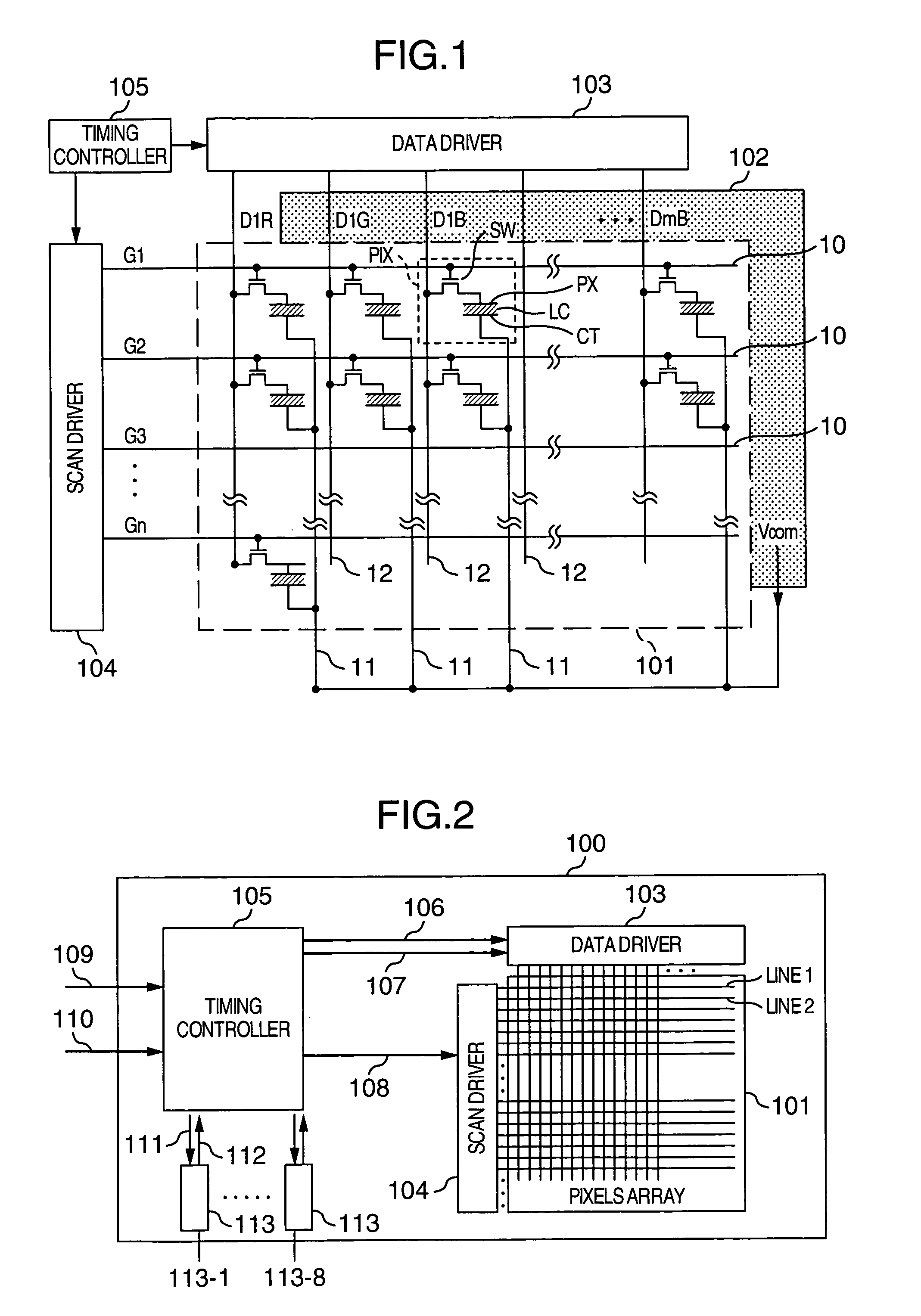
[0051]The operation of the data driver to write a tone voltage of video data or blanking data in each pixel PIX is conducted during a period of time in which the gate signal is being generated in each associated gate line. After a gate signal is generated on a gate line on which video data is to be written, a jump voltage and a rewrite voltage fluctuate due to a gate wave delay at a falling edge of the gate signal. FIG. 6 shows a configuration of a pixel in which a jump voltage due to Cgs caused by a characteristic of a...
PUM
 Abstract
Description
Claims
Application Information
 - Generate Ideas
- Intellectual Property
- Life Sciences
- Materials
- Tech Scout
- Unparalleled Data Quality
- Higher Quality Content
- 60% Fewer Hallucinations
Browse by: Latest US Patents, China's latest patents, Technical Efficacy Thesaurus, Application Domain, Technology Topic, Popular Technical Reports.
© 2025 PatSnap. All rights reserved.Legal|Privacy policy|Modern Slavery Act Transparency Statement|Sitemap|About US| Contact US: help@patsnap.com