
Unpowered twisted pair loopback circuit for differential mode signaling

a loopback circuit and differential mode technology, applied in pulse techniques, multiple input and output pulse circuits, interconnection arrangements, etc., can solve problems such as potential computer network problems, mechanical relays are relatively expensive and can become unreliable, andphantom power could damage or operate improperly with certain non-compatibility dte equipmen

Active Publication Date: 2008-11-04
CISCO TECH INC
View PDF34 Cites 12 Cited by
  • Summary
  • Abstract
  • Description
  • Claims
  • Application Information

AI Technical Summary

Problems solved by technology

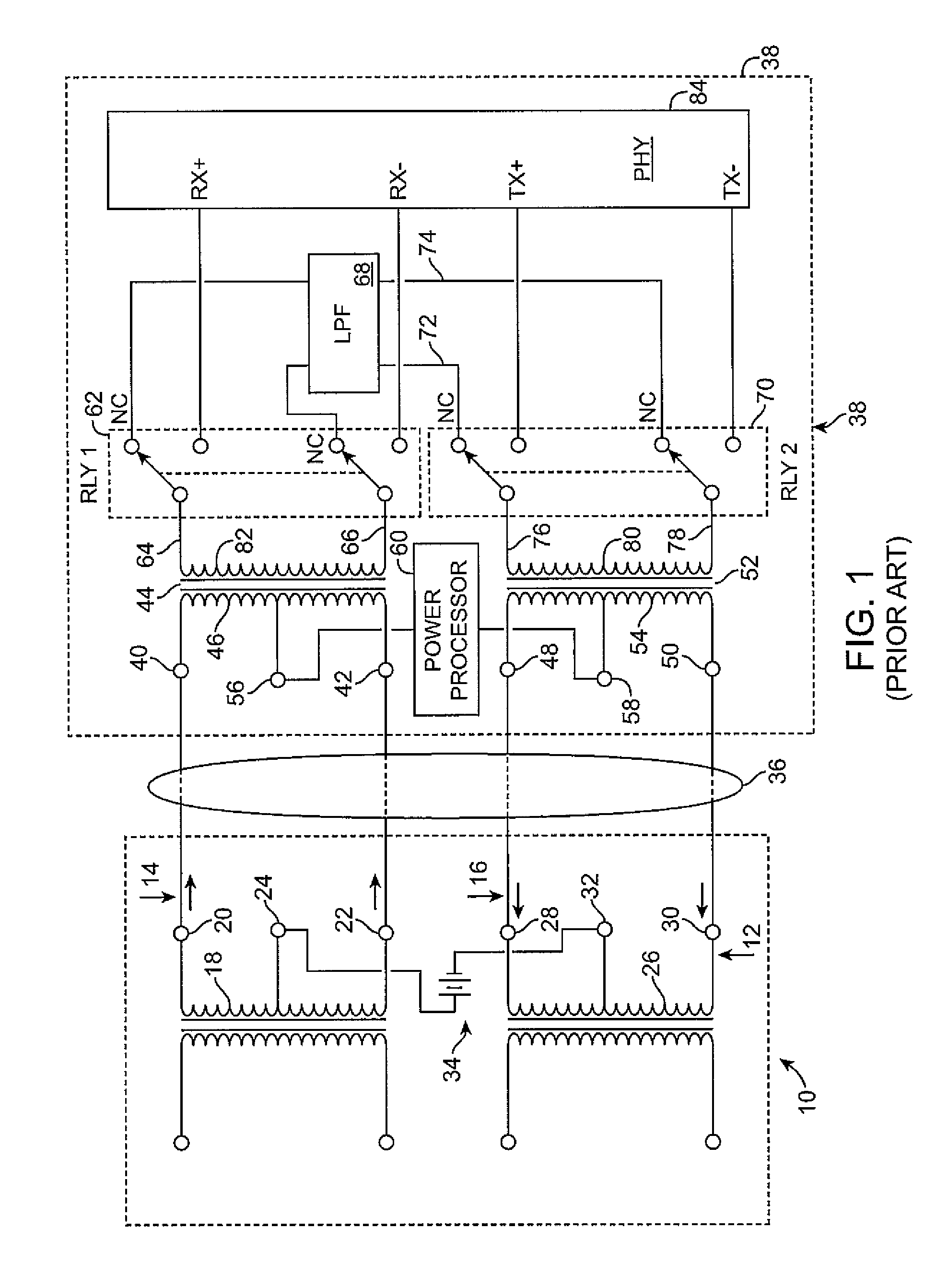
Where the IP telephones are compatible and thus adapted to receive phantom power over the twisted pair connection to the switch, it is desirable for the switch to verify the compatibility before applying the phantom power because it is conceivable that the phantom power could damage or operate improperly with certain non-compatible DTE equipment (“legacy equipment”) which might also be connected to the switch.
This is undesirable for data signals under certain circumstances as it can lead to certain kinds of potential computer network problems.
Such mechanical relays are relatively expensive and can become unreliable.
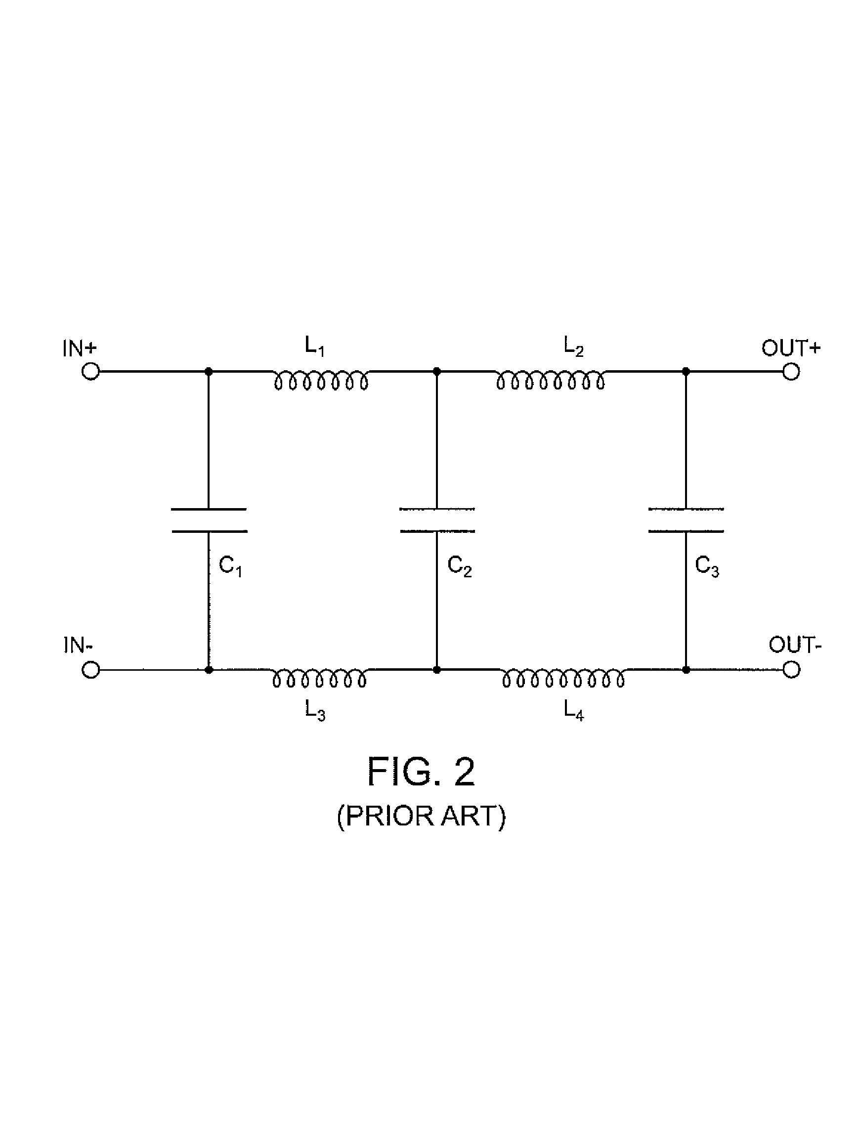
Low pass filters composed of inductors and capacitors also consume volume in the DTE equipment and can be relatively expensive to deploy.
Such devices are difficult to integrate onto an integrated circuit with current technology and thus must actually be fabricated with discreet components or is known to those of ordinary skill in the art.
Furthermore, relays can wear out and / or suffer from intermittent failures and are thus not considered to be the most reliable of electronic devices.

Method used


Image

  • Unpowered twisted pair loopback circuit for differential mode signaling
  • Unpowered twisted pair loopback circuit for differential mode signaling
  • Unpowered twisted pair loopback circuit for differential mode signaling

Examples


Embodiment Construction

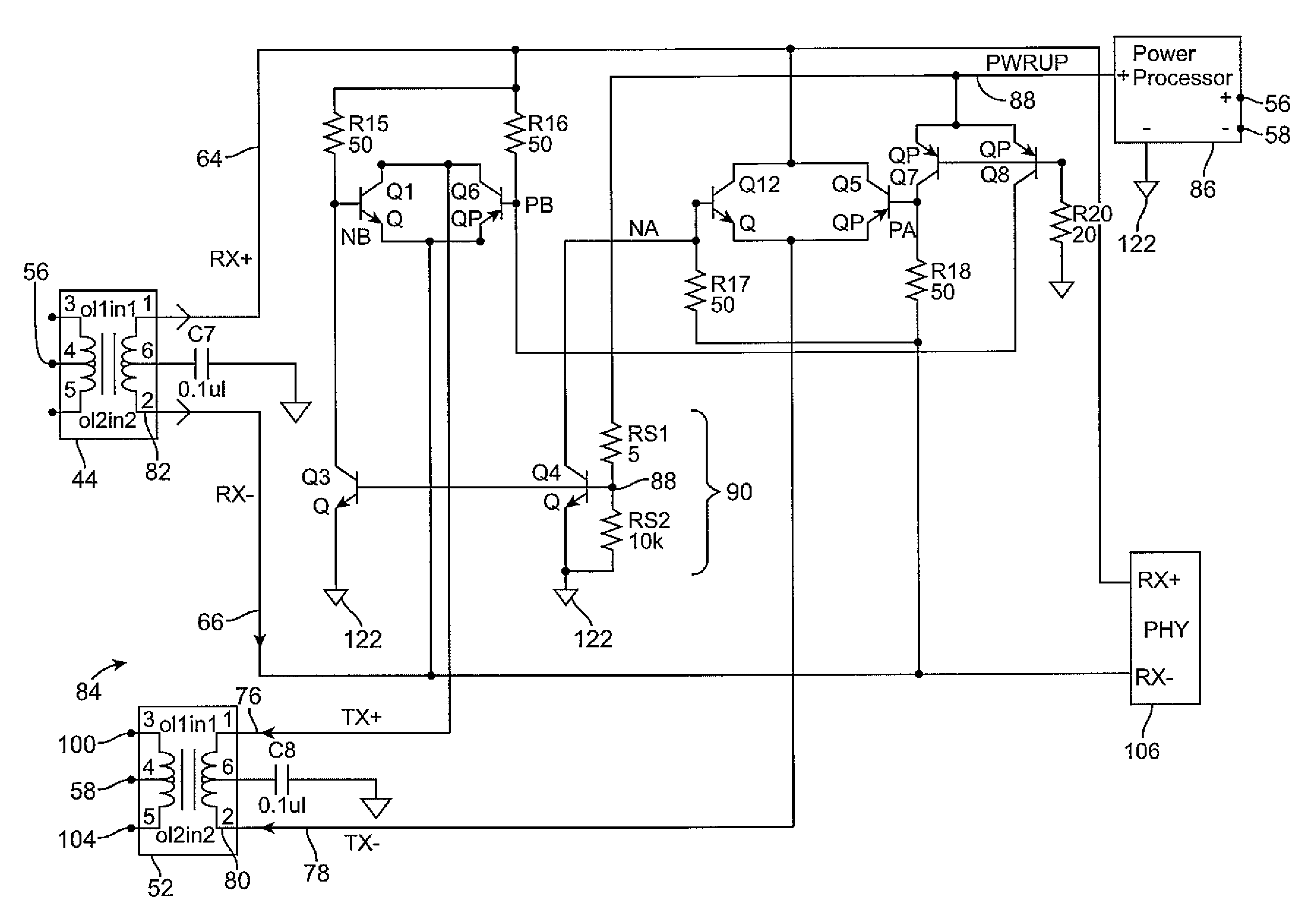
[0035]Embodiments of the present invention are described herein in the context of a method and apparatus for controlling loop back of a differential mode signal through a remote device without the use of a powered circuit or a relay at the remote device. Those of ordinary skill in the art will realize that the following description of the present invention is illustrative only and not intended to be in any way limiting. Other embodiments of the invention will readily suggest themselves to such skilled persons having the benefit of this disclosure. Reference will now be made in detail to a number of implementations of the present invention as illustrated in the accompanying drawings. The same reference numbers will be used throughout the drawings and the following description to refer to the same or like parts.

[0036]In the interest of clarity, not all of the routine features of the implementations described herein are described. It will of course be appreciated that in the developmen...


PUM


Abstract

A method and apparatus provide an IP telephone or similar device with a mechanism to receive and at least briefly loop back discovery signals received from a telecommunications device such as an Ethernet switch while not permitting the loop back of data packet signals. No mechanical relays are required and the circuitry can be fully integrated on an integrated circuit using commonly available techniques, if desired.

Description

FIELD OF THE INVENTION[0001]The present invention relates to a method and an apparatus for detecting the presence of a connected device of a particular class, such as a telephone, that may require phantom power to be supplied over twisted pair wiring. Discovery signals transmitted on ports of a telecommunications device, such as a switch, need to be looped back to the telecommunications device to indicate the presence of the particular connected device (the absence of the particular device being inferred by the absence of the loop back signal). Accordingly, the discovery signal should not be looped back if the device is absent or if a connected device is not of the particular type.BACKGROUND OF THE INVENTION[0002]Telephones and other types of data terminal equipment (DTE) are routinely used for voice, data traffic and other forms of telecommunication. Such DTE equipment typically is wired with twisted pair wire to a switch or similar telecommunications device. For example, some comm...

Claims


Application Information

Patent Timeline
IPC IPC(8): H04M1/00H04L5/20
CPCH04L5/20
Inventor MOLENDA, JAMESDE NICOLO, MAURILIO TAZIONAKAMURA, KARLKARAM, ROGER
Owner CISCO TECH INC
Learn More