Pointing device inertial isolation and alignment mounting system

a technology of inertial isolation and mounting system, which is applied in the field of mortars, can solve the problems of the attachment structure, the prior art pdmas (pointing device mounting assembly) cannot withstand the recoil acceleration force, and the attachment structure cannot be retracted, so as to achieve the effect of being easy to build and maintain

Inactive Publication Date: 2008-11-11
HONEYWELL INT INC
View PDF4 Cites 19 Cited by
  • Summary
  • Abstract
  • Description
  • Claims
  • Application Information

AI Technical Summary

Benefits of technology

[0016]A primary advantage of the present invention is that it suspends the carrier along with the electronic device during a firing event thus, isolating the electronic device from any imparted linear shock.
[0017]Another advantage of the present invention is it is inexpensive to build and maintain.
[0018]Yet another advantage of the present invention is that it can be utilized for many different vehicle mounted and ground based free standing weapon systems.

Problems solved by technology

A sensitive electronic pointing device, such as inertial measurement unit or inertial navigation unit, and its attachment structure would be, and has been, destroyed by this extreme acceleration and deceleration.
Presently the prior art PDMAs (pointing device mounting assembly) cannot withstand the recoil acceleration force while attached to a 120 mm mortar barrel when fired while mounted on a mortar weapon, such as the M9, base plate in the dismounted configuration.
The present prior art PDMA experiences catastrophic failure of the steel mounting plates due to stress in excess of the bending moment of the material of their construction.
This force exceeds the isolators travel limit and transfers the shock load into the RLG pointing device and causes internal physical damage.
Problematic with the present design is the fact that plate alignment during attachment to the barrel is not easily indexed and this design cannot be used on the mortar barrel when fired from a base plate dismounted configuration due to the high gravity (g) load caused by the force of acceleration over the seating travel distance.
This configuration has in the past bent and broken the steel plates and exceeded the shock isolation limits to the RLG pointing device.
The attempt in the prior art to design a mechanical force vector isolation system for the RLG pointing device fails to address the requirement for symmetry and even distribution of force throughout its design.
This causes the shaft and bearing assembly to seize and transfer the recoil force into the bi-pod attachment collar causing it to slip.
The magnitude of the forces has caused the materials of construction in this prior art design to fail.

Method used


Image

  • Pointing device inertial isolation and alignment mounting system
  • Pointing device inertial isolation and alignment mounting system
  • Pointing device inertial isolation and alignment mounting system

Examples


Embodiment Construction

)

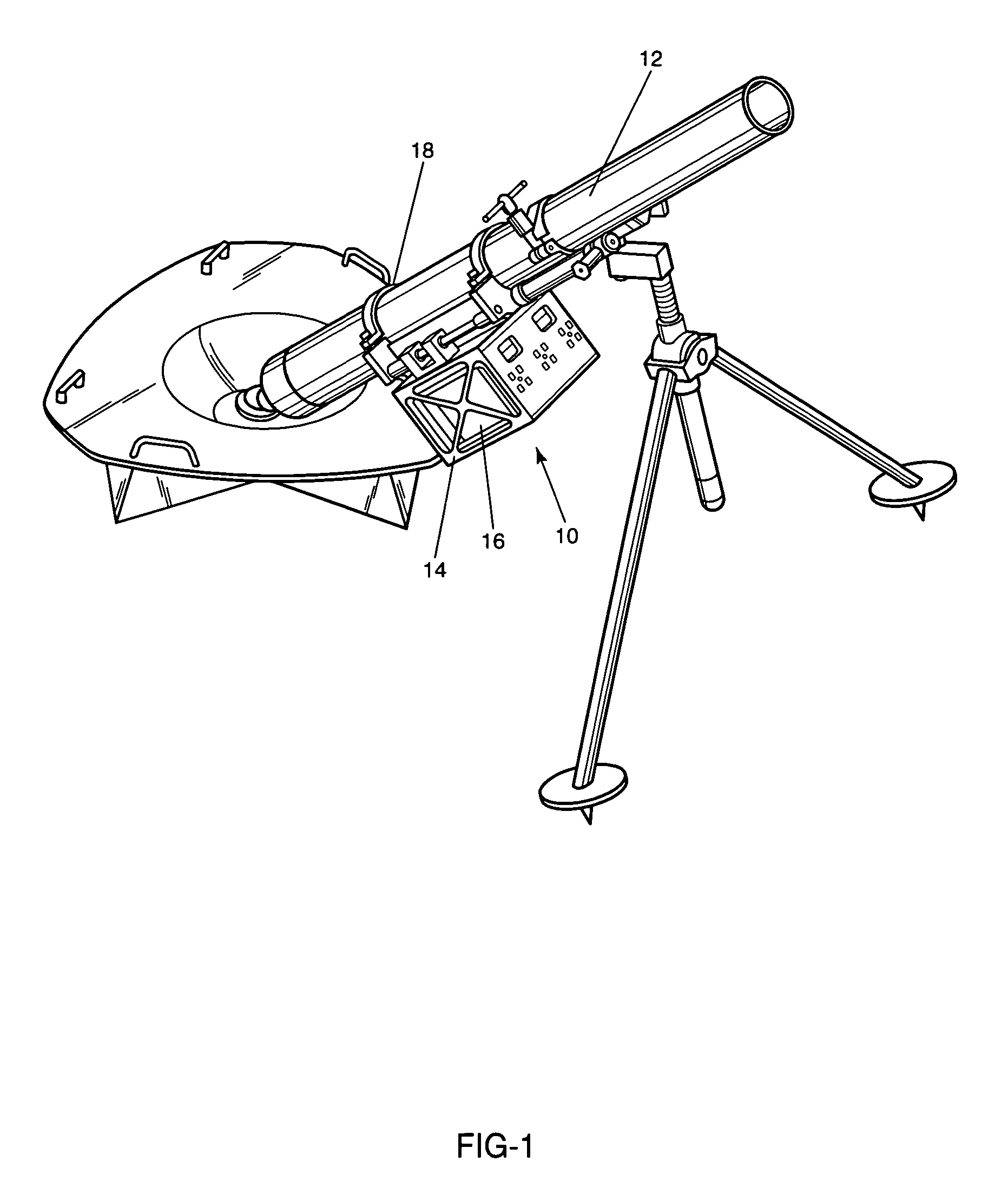
[0028]Disclosed is the preferred embodiment of a mounting structure 10 for mounting a sensitive component such as a pointing device to a mortar, or the like. FIG. 1 shows a perspective view of mounting structure 10, affixed to a mortar tube or barrel 12. As can be seen, mounting structure 10 has a cage 14 to encase the pointing device 16, such as a TALIN™, and a clamping mechanism 18 to secure mounting structure 10 to mortar tube 12.

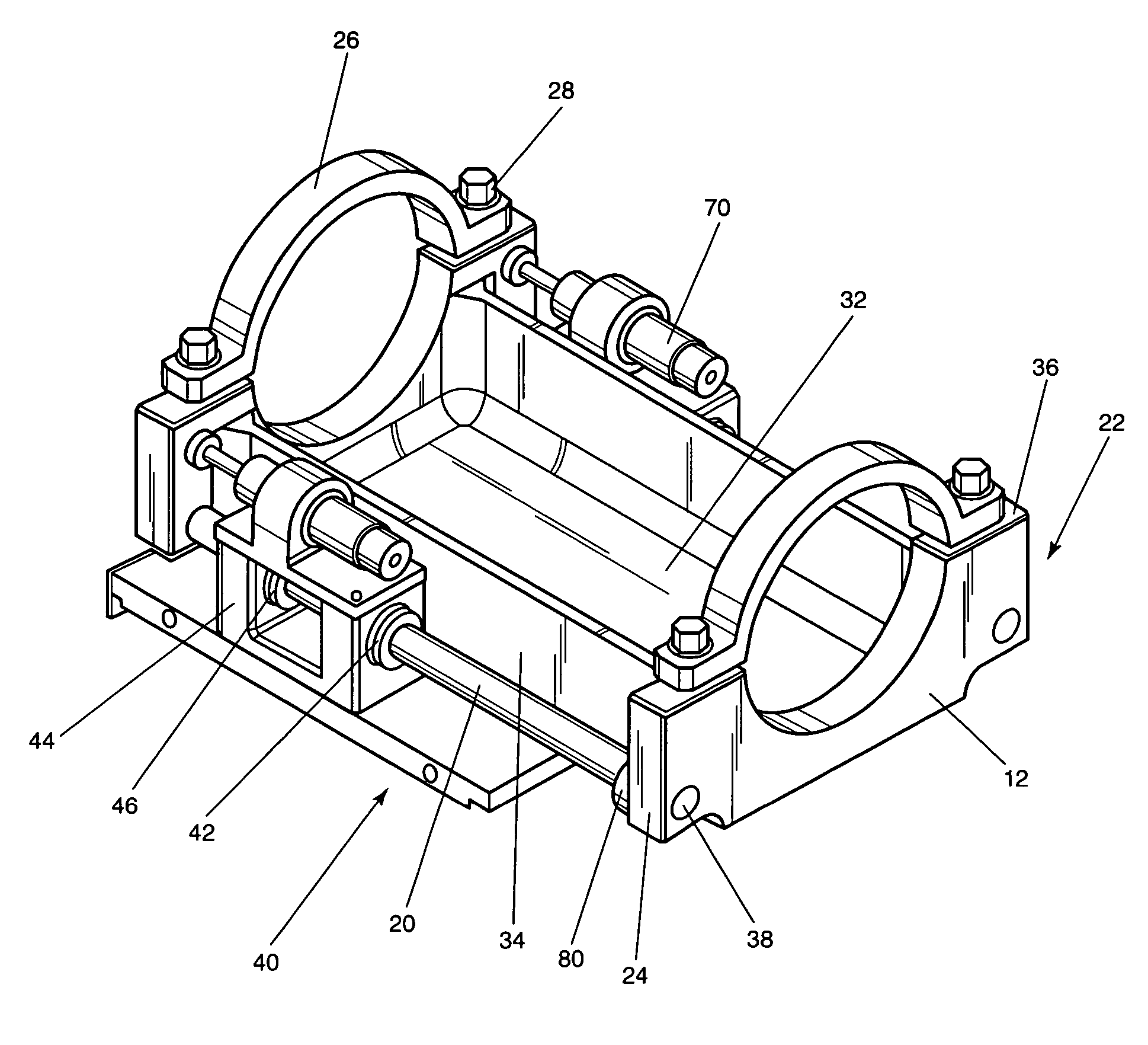
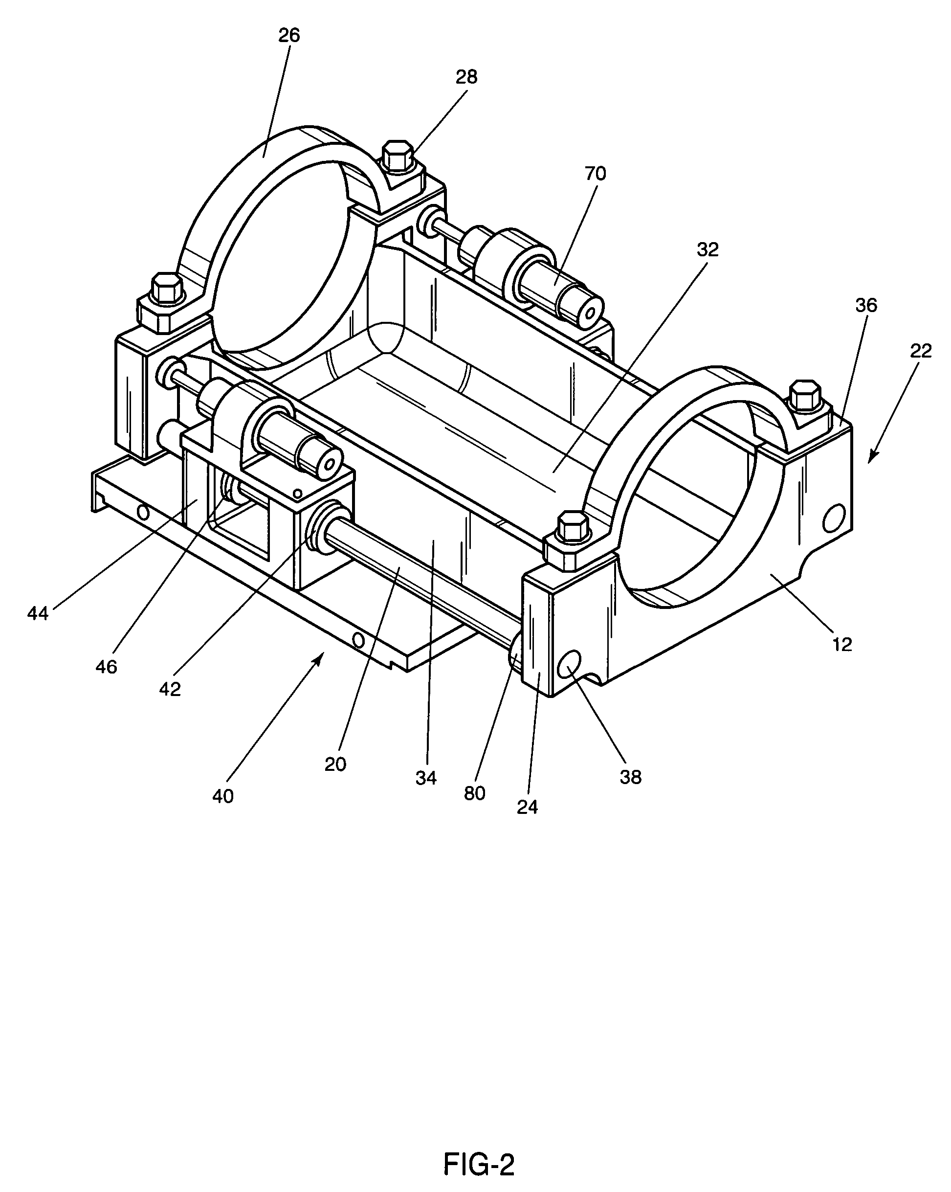
[0029]FIG. 2 is a perspective top view of the preferred mounting structure. The first part of this embodiment is clamping mechanism 18 which mounts to mortar tube 12. Clamping mechanism 18 will anchor and position steel shafts 20 parallel to mortar tube 12. A typical mortar barrel 12 is a tube or a round pipe approximately five inches (5″) in diameter and five feet (5′) long. Steel shafts 20 are approximately twelve inches (12″) long and need to be held perfectly parallel to the barrel 12 by clamping mechanism 18 comprising a saddle structure 22, and sa...


PUM


Abstract

An isolation system for a sensitive component or apparatus affixed to a mortar tube comprising a barrel mount assembly which supports two parallel shafts. A plate parallel with each axis of the two shafts positions four bearing carrier blocks, two each containing a sleeve bearing which rides on each of the shafts to allow the plate assembly to slide freely along the length of the shafts and support an isolated cage. During firing, the travel vector is decoupled from the cage by the shafts as they move with the barrel through the bearings leaving the cage assembly in free space. The cage then accelerates under the force of gravity over the distance of the displaced travel of the shafts back to its rest position landing on steel springs or dampers, each on a shaft and seated against the lower flange end of the barrel mount assembly.

Description

CROSS-REFERENCE TO RELATED APPLICATIONS[0001]This application is based on U.S. Provisional Application Ser. No. 60 / 638,244 entitled “Pointing device inertial isolation and alignment mounting system.” filed on Dec. 21, 2004, the teachings of which are incorporated herein by reference.BACKGROUND OF THE INVENTION[0002]1. Field of the Invention (Technical Field)[0003]The present invention relates to mortars and more particularly to a method and apparatus for isolating a linear shock while maintaining the alignment of a sensitive electronic pointing device for use on a barrel of mortar or similar device.[0004]2. Background Art[0005]During the firing of a large bore weapon a significant reaction force is imparted to the barrel and support structure. A support structure, which is required to travel a certain distance before absorbing the load, allows the barrel and its attached components to undergo an instantaneous high-g acceleration. A sensitive electronic pointing device, such as inert...

Claims


Application Information

Patent Timeline
Patent Type & Authority Patents(United States)
IPC IPC(8): F41F1/06
CPCF41F1/06F41G11/002F41G11/004
Inventor SHIPMAN, JOHN M.JUDKINS, ERIC T.MANTYCH, GLENBURKHOLDER, DANIEL E.
Owner HONEYWELL INT INC
Why Eureka
Try Eureka