
Rapid prototype casting

a prototype casting and prototype technology, applied in the direction of foundry moulding apparatus, manufacturing tools, foundry patterns, etc., can solve the problems of complex geometry of components, difficult casting, and high cost of tooling for such parts, and achieve the effect of reducing production costs and time-consuming

Inactive Publication Date: 2008-11-11
HONEYWELL INT INC
View PDF12 Cites 43 Cited by
  • Summary
  • Abstract
  • Description
  • Claims
  • Application Information

AI Technical Summary

Problems solved by technology

Components having complex geometry, such as components having internal passages and voids therein, are difficult to cast using conventional methods; tooling for such parts is both expensive and time consuming, for example, requiring a lead-time of at least four months.
This situation is exacerbated by the nature of conventional molds comprising a shell and one or more separately formed cores, wherein the core(s) are prone to shift during casting, leading to low casting tolerances and low casting efficiency (yield).
Examples of components having complex geometry and which are difficult to cast using conventional methods, include hollow airfoils for gas turbine engines, and in particular relatively small, double-walled airfoils.
Such prior art methods are not only expensive and have long lead-times, but have the disadvantage of low casting yield, for example, due to lack of reliable registration between the core and shell allowing movement of the core relative to the shell during filling the mold with molten metal.
In the case of hollow airfoils, another disadvantage of such prior art methods is that shaped film holes must be formed by an expensive, separate step after forming the cast part, for example, by electron discharge machining (EDM) or laser drilling.
Development time and cost for airfoils, such as turbine blades, are magnified because such components generally require several iterations, sometimes while the part is in production.
To meet durability requirements, turbine blades are often designed with increased thickness and with increased cooling airflow capability in an attempt to compensate for poor casting tolerance, resulting in decreased engine efficiency and lower engine thrust.
Neither Cooper et al. nor Klug et al. disclose a method for rapid prototyping metal components.

Method used


Image

  • Rapid prototype casting
  • Rapid prototype casting
  • Rapid prototype casting

Examples


Embodiment Construction

[0020]The following detailed description is of the best currently contemplated modes of carrying out the invention. The description is not to be taken in a limiting sense, but is made merely for the purpose of illustrating the general principles of the invention, since the scope of the invention is best defined by the appended claims.

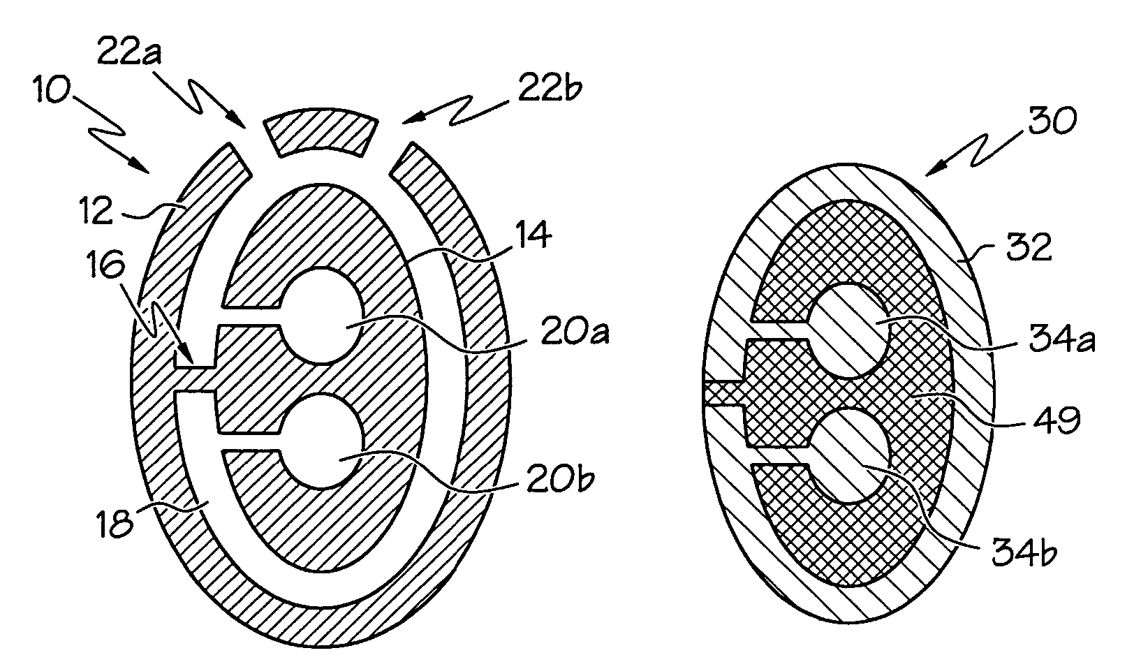
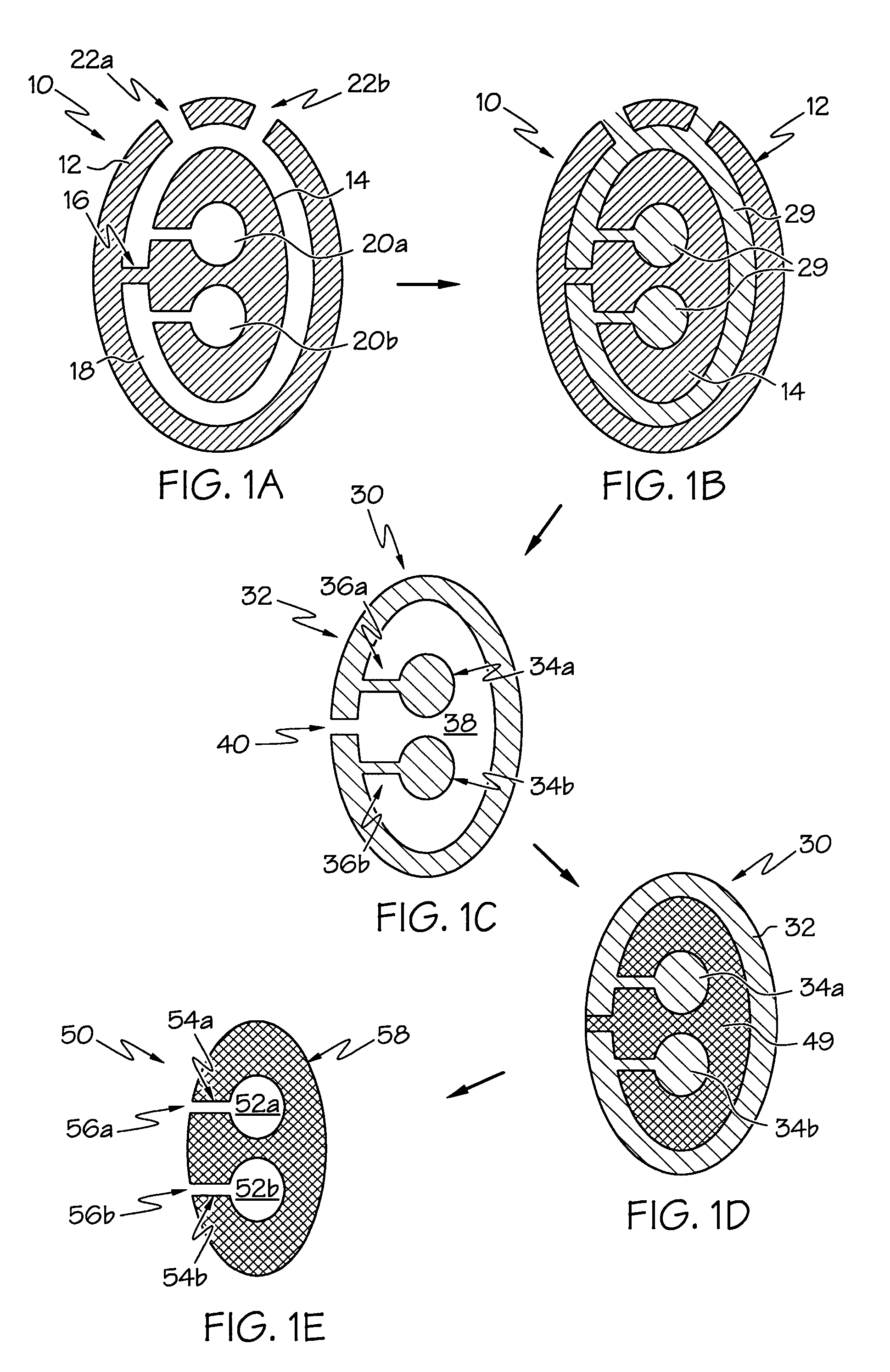
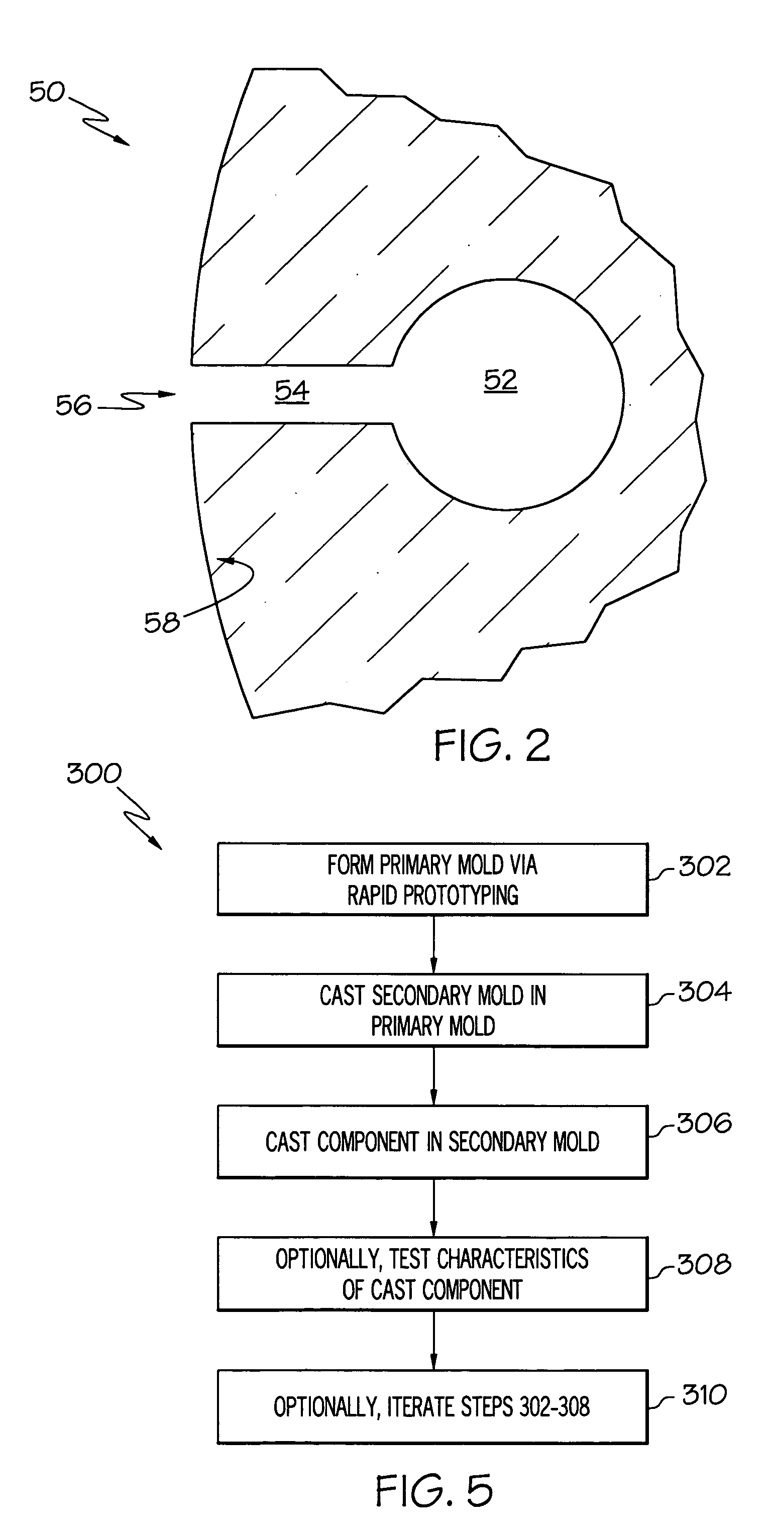
[0021]Broadly, the present invention provides metal components and methods for making such components. The present invention may be used to provide metal components having complex geometry and one or more internal voids therein. The present invention may incorporate a rapid prototyping process to decrease time between iterations in designing metal components having complex geometry, and to shorten production lead-time of the metal components. As a non-limiting example, the present invention may be used to form metal rotor blades and stator vanes for a gas turbine engine. Such blades and vanes may be hollow, may be single- or double-walled, and may have ...


PUM

PropertyMeasurementUnit
thicknessaaaaaaaaaa
thicknessaaaaaaaaaa
lead-timeaaaaaaaaaa

Abstract

Methods for rapid prototype casting metal components, wherein the metal components are cast in a secondary ceramic mold, the secondary ceramic mold is cast in a primary mold, and the primary mold is formed by rapid prototyping or rapid manufacturing. The secondary ceramic mold may comprise a one-piece integral shell and core(s), and the metal components may have at least one hollow portion or void therein, such as a hollow airfoil for a gas turbine engine.

Description

BACKGROUND OF THE INVENTION[0001]The present invention relates to methods for rapid prototyping metal components, and in particular to casting of hollow metal components in a secondary mold having an integral core and shell, the secondary mold being formed from a rapid prototyped primary mold.[0002]Components having complex geometry, such as components having internal passages and voids therein, are difficult to cast using conventional methods; tooling for such parts is both expensive and time consuming, for example, requiring a lead-time of at least four months. This situation is exacerbated by the nature of conventional molds comprising a shell and one or more separately formed cores, wherein the core(s) are prone to shift during casting, leading to low casting tolerances and low casting efficiency (yield). Examples of components having complex geometry and which are difficult to cast using conventional methods, include hollow airfoils for gas turbine engines, and in particular re...

Claims


Application Information

Patent Timeline
Patent Type & Authority Patents(United States)
IPC IPC(8): B22C9/00
CPCB22C7/00B22C9/04B22C9/24B33Y80/00
Inventor ORTIZ, MILTONMALAK, MALAK F.HALFMANN, STEVE H.
Owner HONEYWELL INT INC
Learn More