Al technical title is built by PatSnap Al team. It summarizes the technical point description of the patent document.
a heat trace system and pipe technology, applied in the direction of heater elements, lighting and heating equipment, heater arrangements, etc., can solve the problems of increased bulk, heat loss, difficulty, etc., and achieve the effect of facilitating approval
Active Publication Date: 2008-11-11
BENCH STEVEN D
View PDF14 Cites 7 Cited by
Summary
Abstract
Description
Claims
Application Information
AI Technical Summary
This helps you quickly interpret patents by identifying the three key elements:
Problems solved by technology
Method used
Benefits of technology
[0015]It is therefore the primary object of the invention to overcome this specific long felt need by using a coiled wire heating element inside the pipe or hose which eliminates the reliability problem almost entirely. The coiled wire is basically the same as used conventionally on telephones often referred to as retractable coiled cord. The connection through the piping is accomplished using watertight connectors on the entrance and exit points in the piping which have been proven to be watertight and reliable since these connectors have been in use for years in their basic form and are well known in the industry. This type of coiled wire eliminates broken or damaged heating elements as it flexes inside a hose and is not affected by expansion and contraction of the water inside of the piping system.
[0019]A further object of the invention utilizes low voltage which has many advantages over line voltage as it is safer relative to human intervention and since the voltage is under 30 volts AC the governing safety code regulations are much less restrictive making the system easier to be approved by various airport authorities.
Problems solved by technology
While this type of heating system functions fairly well in general practice some difficulties occur when used for water serviced by the airports to provide service and potable water to the aircraft adjacent to a passenger loading bridge.
Additional bulk is created along with some heat loss when the heat source is on the outside.
Wrapping around fittings and connectors often causes voids which by their very nature prevent full coverage as well as problems of an overall unsightly appearance.
Further when a flexible hose is required the problem is increased as the hose flexibility may be seriously impaired.
There have been some piping systems in the past that were developed specifically for airports that simply used insulated wires within the pipes and hoses however the expansion, contraction and damage created by collapsing, coiling and spooling frequency of a hose created reliability problems.
Method used
Image
Click on the blue label to locate the original text in one second.
Reading with bidirectional positioning of images and text.
Examples
Embodiment Construction
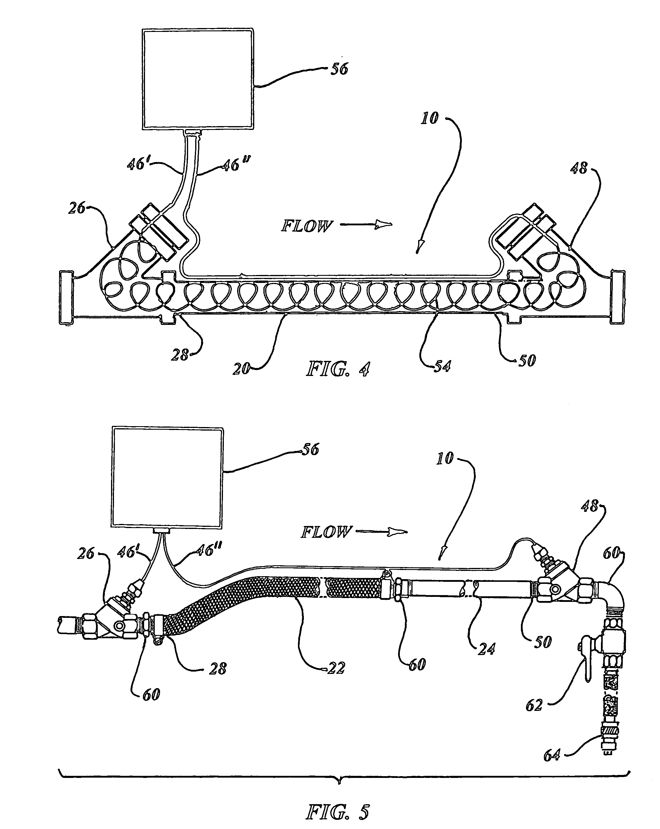
[0047]The best mode for carrying out the invention is presented in terms of a preferred and a second embodiment. The difference between embodiments is in the type and configuration of the coiled wire with the preferred embodiment using a single conductor and the second embodiment a two conductor type. Obviously the fittings must differ slightly to accommodate the different number of conductors.
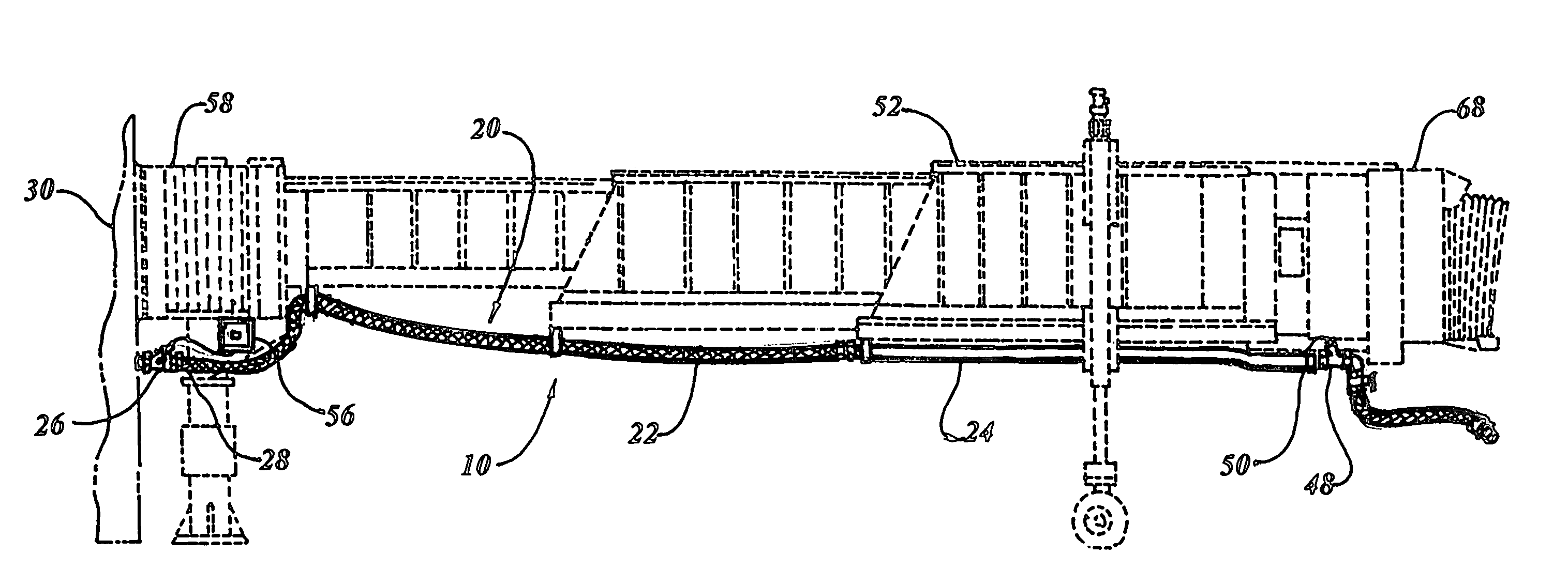
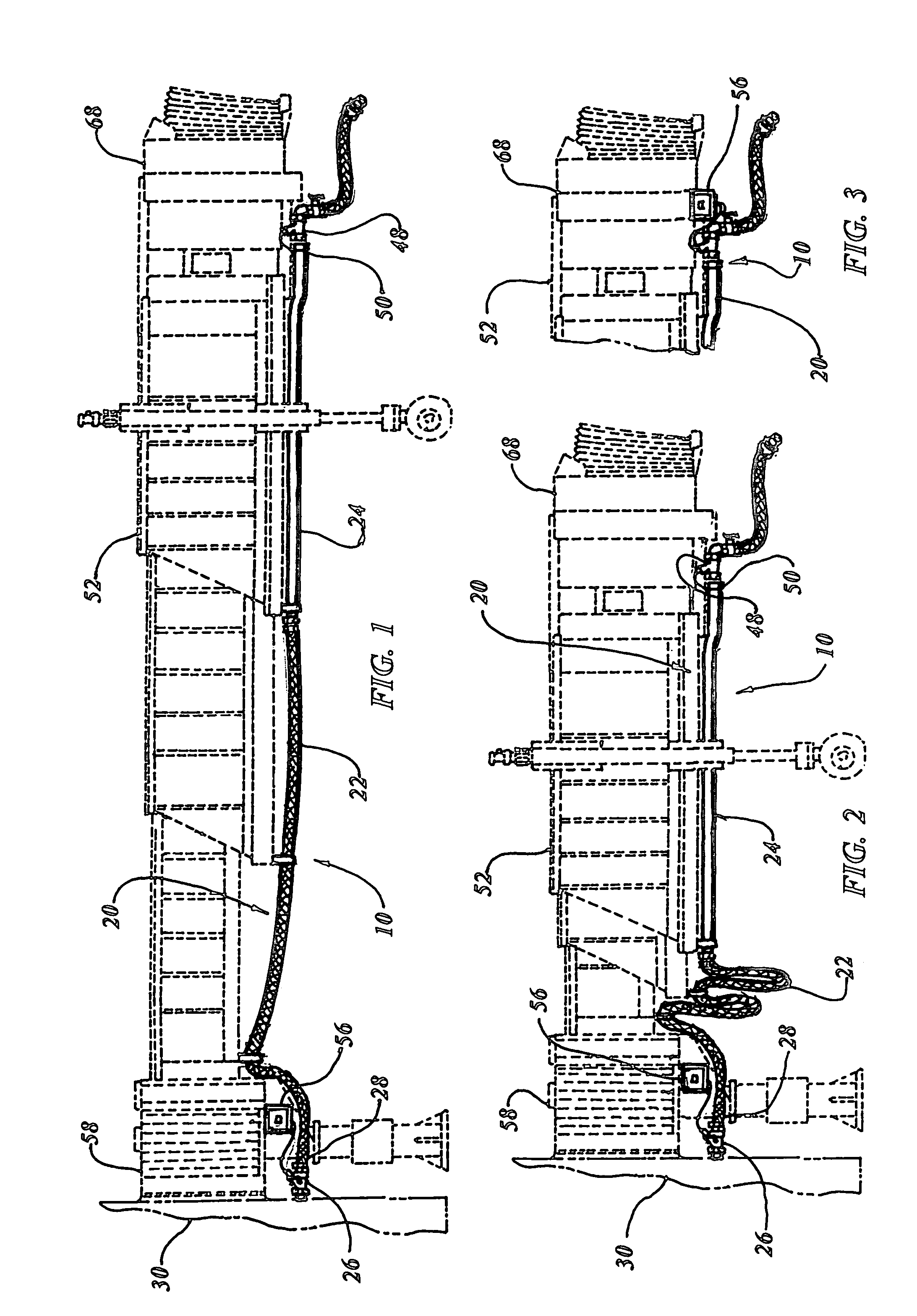
[0048]The preferred embodiment of the in-pipe heat trace system 10 for heating water servicing conduits for the prevention of freezing is shown in FIGS. 1, 2 and 4-11 and is comprised of
[0049]A passageway of any type, a round passageway or a single conduit 20 capable of conducting city water to an aircraft positioned at a passenger loading bridge 52 is employed in the system 10. The preferred embodiment of the conduit 20 is illustrated in FIGS. 1, 2 and 5-7. The passageway in an acceptable configuration however, may be any type of system capable of conducting fluid in varied applications with ...
PUM
Abstract
A heat trace system (10) is used for heating water to prevent freezing in a conduit (20) while servicing an aircraft positioned at a passenger loading bridge (52). An upstream fitting (26) is attached onto the conduit adjacent to a building structure and a downstream fitting (48) is attached onto the conduit adjacent to the cab of the passenger loading bridge. A coated retractable coiled wire disposed within the conduit and cold lead wires (46) enter through the upstream fitting and leave through the downstream fitting. A low voltage solid state power control box (56) is in communication with the cold lead attached to the coiled wire inside providing regulated electrical energy for heating the coiled wire thus preventing freezing the water within in the conduit.
Description
TECHNICAL FIELD[0001]The present invention relates to heating liquid within pipes in general. More specifically to a system that incorporates a coiled coated wire disposed within a water pipe to prevent freezing while servicing aircraft at a loading gate.BACKGROUND ART[0002]Previously, many types of heating systems have been used in endeavoring to provide an effective means to heat liquids within a pipe or chamber.[0003]A search of the prior art did not disclose any patents that possess the novelty of the instant invention; however the following U.S. patents are considered related:[0004]U.S. Pat. No.InventorIssue Date3,378,673HopperApr. 16, 19683,716,693BleckmannFeb. 13, 19735,408,579HuntApr. 18, 19955,497,824RoufMar. 12, 19965,774,627JacksonJun. 30, 19986,078,730Huddart et al.Jun. 20, 20006,539,171 B2VonArx et al.Mar. 25, 2003[0005]Bleckmann in U.S. Pat. No. 3,716,693 discloses an electrical tubular heating element consisting of a metal outer tube with heating resistance arranged i...
Claims
Application Information
Patent Timeline
Application Date:The date an application was filed.
Publication Date:The date a patent or application was officially published.
First Publication Date:The earliest publication date of a patent with the same application number.
Issue Date:Publication date of the patent grant document.
PCT Entry Date:The Entry date of PCT National Phase.
Estimated Expiry Date:The statutory expiry date of a patent right according to the Patent Law, and it is the longest term of protection that the patent right can achieve without the termination of the patent right due to other reasons(Term extension factor has been taken into account ).
Invalid Date:Actual expiry date is based on effective date or publication date of legal transaction data of invalid patent.