Multi-user autostereoscopic display with position tracking

a multi-user, position tracking technology, applied in surveying, navigation, printing, etc., can solve the problems of multi-user operation, difficult practical realization of such a multi-user display, and disadvantages of using a diffuser plate, so as to achieve low cost, low cost, and low labor intensity

Inactive Publication Date: 2008-11-11
SEEREAL TECHNOLOGIES
View PDF14 Cites 71 Cited by
  • Summary
  • Abstract
  • Description
  • Claims
  • Application Information

AI Technical Summary

Benefits of technology

[0029]The present invention relates to an autostereoscopic display that can be used by several observers simultaniously, a so-called multi-user display, controlled by a tracking and image controller, said display being characterised by low cost and little labour for the individual components and their alignment, flat design, possibility of replacing optical components having various geometries, and great brightness, and said display preventing the disadvantage of the above-discussed solution, in particular the restrictions to the tracking ability of the sweet-spot unit, and said display minimising aberrations and thus substantially improving the quality and foremost the homogeneity of the viewed images.
[0032]In contrast, the focal distance of the field lens is much longer than that of the lens elements. The field lens has the function of activating such illumination elements which have almost the same angle to the corresponding lens elements. If possible, the same corresponding illumination elements are thus activated per lens pitch. Like angles to all lens elements ensure a maximum tracking range and minimum aberrations, which is of major importance for homogeneous illumination of the image display matrix.
[0034]This invention has the major advantage that, independently of the position of the lens elements, all active illumination elements have about the same relation to the corresponding lens element, so that the illumination matrix and imaging means must only generate about collimated, parallel bundles of rays directed to the corresponding sweet-spot. Because of the similarity of connection patterns, this makes it possible to use the inventory of illumination elements per lens element more efficiently, thereby increasing the number of positions which can be controlled, thus extending the tracking range of the sweet-spot unit. The inventory of angles which can be used for tracking the sweet-spots is practically the same for all bundles of rays, i.e. it is independent of the location of the bundle of rays in the image display matrix.
[0035]If an observer moves away from his viewing plane, the tracking and image controller with position detector can adapt the direction of the bundles of rays to the detected new distance of the eye positions in the space in front of the display. The identical assignment of illumination elements to the corresponding lenses is minimally disturbed. With this invention, a sufficient inventory of illumination elements remains for each lens element, so that the directions of the bundles of rays can be corrected by changing the activated illumination elements as controlled by the tracking and image controller.
[0042]Further, the field lens may also be a holographic optical element being controllable by the tracking and image controller, said holographic optical element having a variable focal distance in order to improve the tracking range.
[0043]Thanks to the functional and constructional separation of the individual display components it is possible to reduce the demands on the resolution of the illumination matrix. It is only defined by the number of controllable positions or angles. In particular, this solution provides great independence of the image display matrix. This allows, for example, the image display matrix to be replaced for another image display matrix having a higher resolution, as long as the outer dimensions are the same.

Problems solved by technology

However, it is disadvantageous to use a diffuser plate as it generally prevents multi-user operation, since the diffuser plate with its multitude of secondary light sources is represented in periodical continuation through the second lenticular.
A practical realisation of such a multi-user display is rather difficult, because a high-resolution shutter is needed.
Further, matching lens elements, shutter openings and pixels of the image matrix requires extreme precision when manufacturing the components and when aligning them during assembly.
Already little deviations in pixel or segment dimensions or slight misalignment may lead to functional faults.
Further, great resistance of the assembled display to ambient influences, such as temperature fluctuation or vibration, would be required.
Another major disadvantage is represented by the fact that display components cannot be replaced individually.
The disadvantages of this device are a low brightness, because only the light of a locally selectable point light source is available for illuminating the entire image, a large imaging lens and a great depth of the display, which is caused by the three-dimensional backlight.
Further, a three-dimensional backlight is difficult to manufacture.
However, in practice the propagation deviates slightly from this collimation.
This has adverse effects on the practically usable resolution, in particular towards the margins of the illumination matrix 120, where the inventory of controllable positions is reduced.
This represents a significant disadvantage, in particular for the function of an autostereoscopic multi-user display, because a large viewing space and thus a wide range for the tracking and image controller are desirable when two or more observers are in front of the display.
Such lenses cause aberrations, which substantially disturb the homogeneity of the projection through the image display matrix 140.
Because the distance of the illumination elements is always greater than the distance of the lens elements, large angles occur particularly at the margins of the imaging means 110, leading to significant aberrations and thus disturbing the homogeneous illumination of the image display matrix 140.

Method used


Image

  • Multi-user autostereoscopic display with position tracking
  • Multi-user autostereoscopic display with position tracking
  • Multi-user autostereoscopic display with position tracking

Examples


Embodiment Construction

[0052]During the course of this description, like numbers will be used to identify like elements according to the different views that illustrate the invention.

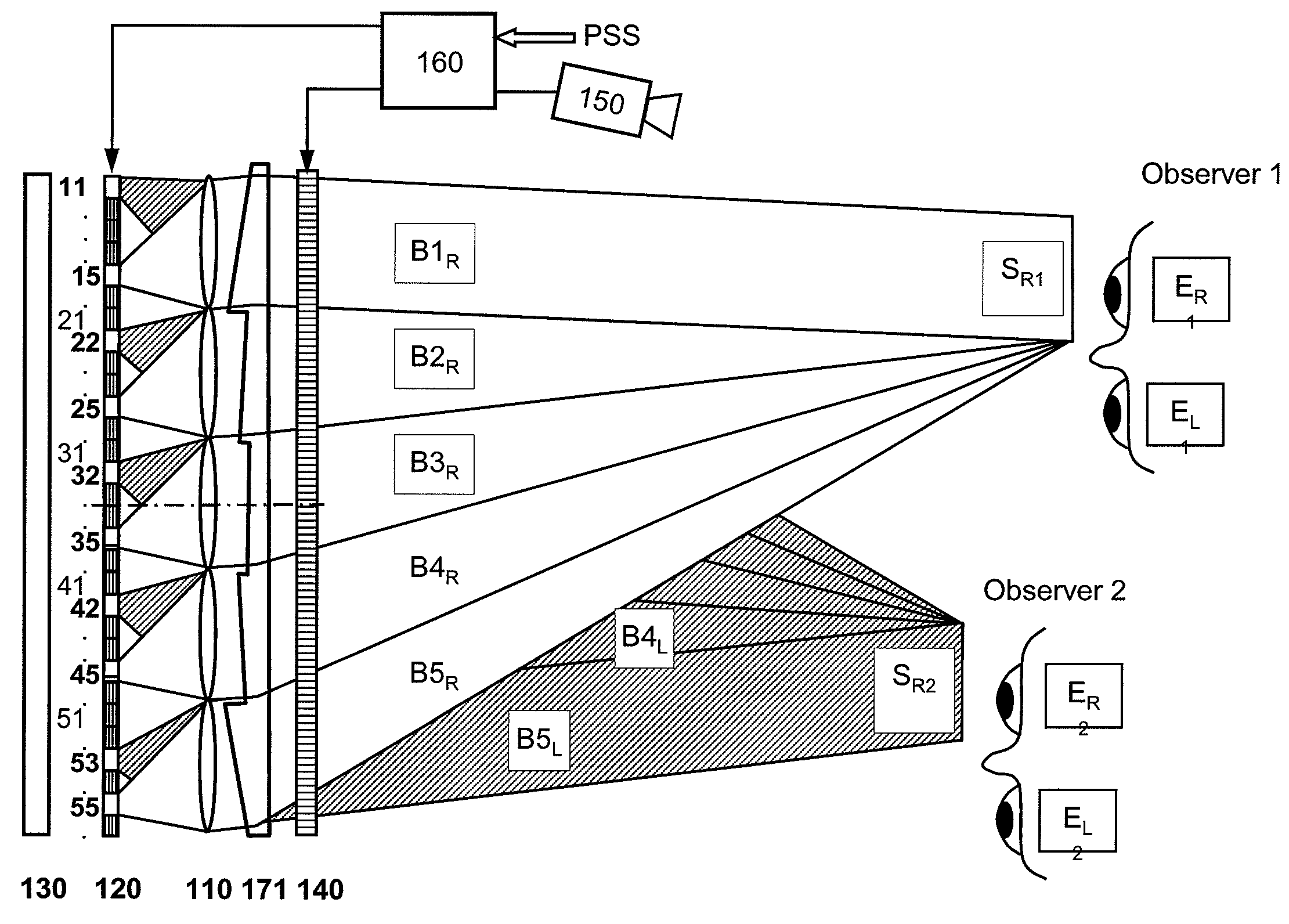
[0053]The autostereoscopic multi-user display according to this invention is described with the help of embodiments and illustrated in the accompanying FIGS. 2-7. Identical functional elements of the autostereoscopic multi-user display according to this invention are denoted by same reference numerals in all figures.

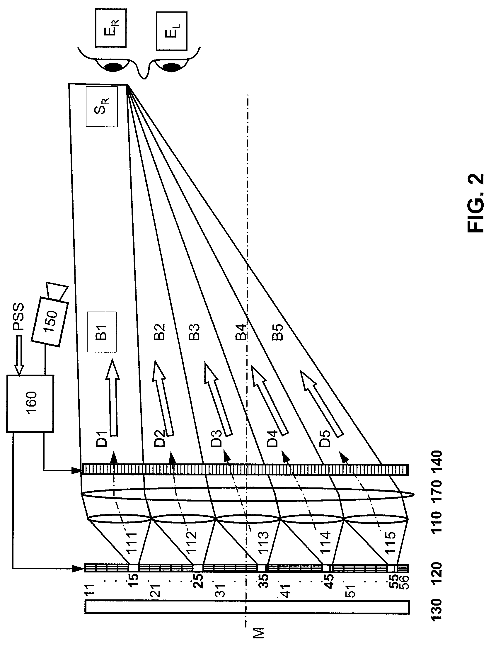
[0054]FIG. 2 shows, with the example of the right eye ER of an observer, the arrangement of elements according to the invention, where numeral 110 denotes an imaging means with lens elements 111-115 and numeral 120 denotes an illumination matrix for generating a bundle of rays B1-B5 for each lens element 111-115. In this embodiment, the illumination matrix 120 is a shutter which uses the light of a large-area light source 130. The shutter contains transmissive illumination elements 11-56. It is an LCD or FLCD pane...


PUM

PropertyMeasurementUnit
widthaaaaaaaaaa
widthaaaaaaaaaa
focal distanceaaaaaaaaaa

Abstract

An autostereoscopic multi-user display comprising a sweet-spot unit which is directionally controlled by a tracking and image control device (160), wherein an illumination matrix (120) is provided with separately activatable illuminating elements (11 . . . 56), in addition to an imaging device used to alternatingly image active illuminating elements, for making expanded sweet spots (SR1 / SR2) visible to various eye positions (EL1 / ER1, EL2 / ER2) of viewers observing alternating images or a stereoscopic image sequence on a transmissive image matrix (140) with the aid of directed beams (B1R . . . B5L). According to the invention, the imaging device comprises an imaging matrix (110) provided with a plurality of lens elements (111 115) whose focal length is small in order to image the active illuminating elements in an enlarged manner onto the sweet spots (SR1 / SR2), and a field lens (171), which follows the imaging matrix (110), in order to keep the distances of the activated illuminating elements between adjacent beams (B1, B2,B4, B5) as constant as possible and in order to assist selection of the directions (D1 . . . D5) with the illumination matrix (120) for the beams.

Description

CROSS REFERENCE TO RELATED APPLICATIONS[0001]This application claims the priority of PCT / DE2004 / 002805 filed on Dec. 17, 2004 and DE 103 59 403.5 filed on Dec. 18, 2003, the entire contents of which are hereby incorporated in total by reference.BACKGROUND OF THE INVENTION[0002]1. Field of the Invention[0003]The present invention relates to an autostereoscopic multi-user display having a sweet-spot unit for focussing light to form bundles of rays directed towards the eyes of one or multiple observers, and an image display matrix for alternate modulation of the light of the sweet-spot unit with two-dimensional images with monoscopic or stereoscopic image sequences. In this document, the term “multi-user display” designates a device which can be used by multiple observers for viewing alternate images of image sequences in the form of 3D scenes simultaneously and independently. The present invention takes advantage of temporal interleaving of single images for each of the observers' eye...

Claims


Application Information

Patent Timeline
Patent Type & Authority Patents(United States)
IPC IPC(8): G02F1/13G02B27/22H04N13/00
CPCG02B27/225H04N13/0404H04N13/047H04N13/0477H04N13/0418H04N13/305H04N13/32H04N13/376H04N13/368G02B30/28G02B27/0093H04N13/00
Inventor SCHWERDTNER, ARMIN
Owner SEEREAL TECHNOLOGIES
Why Eureka
Try Eureka