Power-line communication based surveillance system

a technology of surveillance system and powerline communication, applied in the field of surveillance system, can solve the problems of multiple video imaging devices within current systems, difficult and expensive installation of conventional systems in existing structures, and use of digital, and achieve the effect of low incremental cost and low cos

Active Publication Date: 2008-11-11
SONY CORP +1
View PDF12 Cites 182 Cited by
  • Summary
  • Abstract
  • Description
  • Claims
  • Application Information

AI Technical Summary

Benefits of technology

[0015]Allocation of bandwidth may follow predetermined bandwidth selections, such as in response to user prioritization of image feeds from video imaging devices. Allocation may be driven by events, separately or in combination with user selection. By way of example, one form of event that can drive bandwidth allocation within the present system is that of a motion detection event, preferably generated by a video imaging device, or in association with a location nearby the video imaging device. Dynamic bandwidth allocation, and other aspects of the invention, allow the system to support the use of multiple video cameras within the bandwidth constraints of the power line, without resorting to the routing of high speed optical fiber connections or other similar high-bandwidth connections.
[0016]The present system utilizes a residential network server, such as integrated within a consumer electronics device (i.e. television, set-top box, video recorder, or similar) as a control center unit and storage device (i.e. hard-disk drive or other mass storage device) for the surveillance system, eliminating the need to purchase expensive time lapse video recorders.
[0029]Another aspect of the invention is that of providing a surveillance system that may be manufactured at low cost.
[0030]Another aspect of the invention is that of providing a surveillance system whose functionality may be integrated into existing consumer electronic equipment at low incremental cost.
[0041]Another aspect of the invention is to provide a surveillance network that may securely communicate selected data to a remote location or be controlled from a remote location securely, such as over an Internet connection.

Problems solved by technology

Conventional systems, however, are difficult and expensive to install in existing structures, as installation requires both the installation of a control center and video imagers (i.e. video cameras), along with the routing of cables interconnecting the equipment.
Problems also arise with regard to connecting multiple video imaging devices within current systems, in particular when utilizing analog video feeds which generally require a separate cable connection for each video imager.
Another set of issues surrounds the use of digital networks, (i.e. Ethernet), wherein bandwidth limitation and cost factors arise.
Although the cost of video imagers (i.e. charge-coupled device (CCD) imagers) has dropped below one hundred dollars per unit; the cost of control centers, monitors, and time lapse recording devices are still generally beyond what many consumers, and some commercial institutions, can reasonably justify.

Method used


Image

  • Power-line communication based surveillance system
  • Power-line communication based surveillance system
  • Power-line communication based surveillance system

Examples


Embodiment Construction

[0049]Referring more specifically to the drawings, for illustrative purposes the present invention is embodied in the apparatus generally shown in FIG. 1 through FIG. 3. It will be appreciated that the apparatus may vary as to configuration and as to details of the parts, and that the method may vary as to the specific steps and sequence, without departing from the basic concepts as disclosed herein.

1. System Descriptions

[0050]1.1 Surveillance System

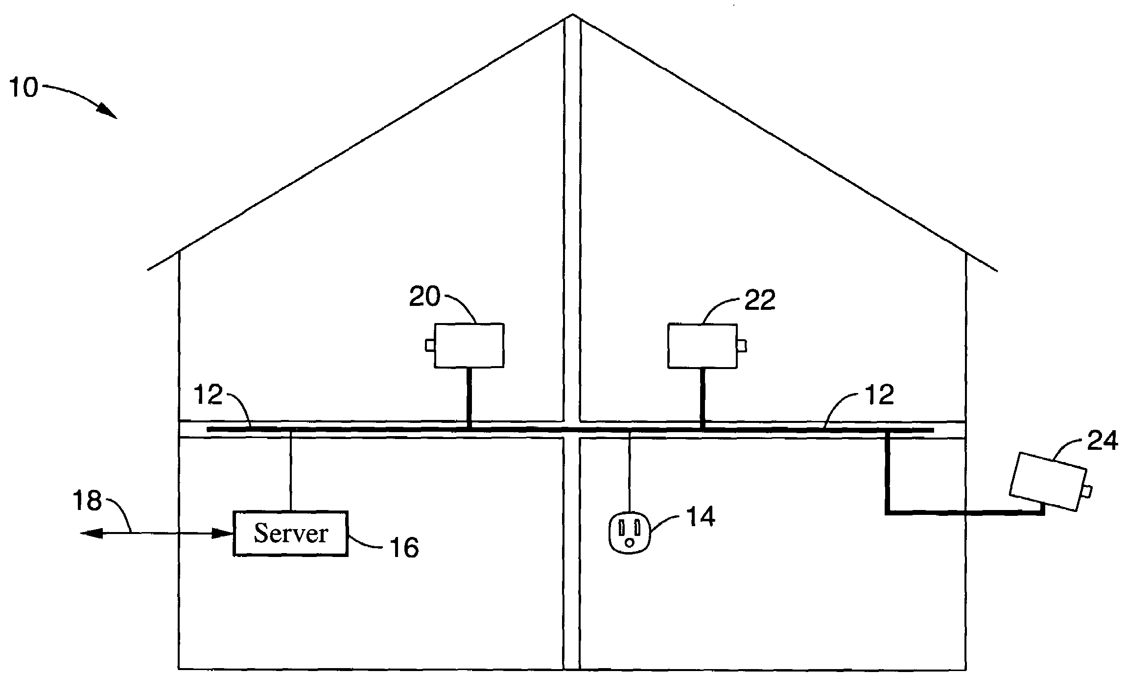
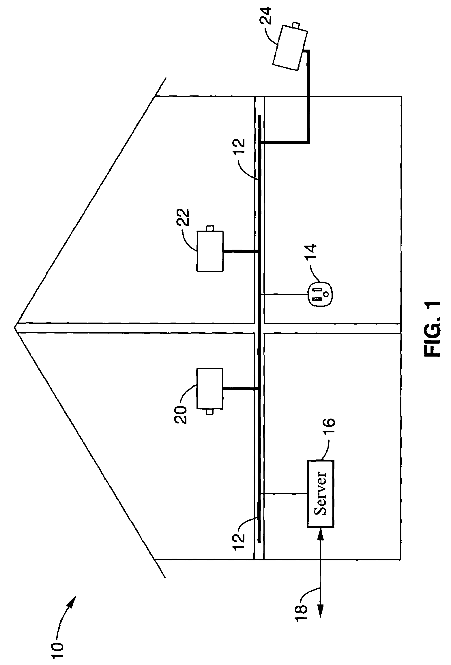
[0051]FIG. 1 illustrates an example of the system shown deployed within a residential structure 10, having power lines 12 routed to multiple outlets, such as represented by outlet 14, in the different rooms and levels within the structure. The system is configured with a server 16 that operates as a control center for the surveillance system and which preferably supports a communication link 18 extending from the structure to an external network, such as a cable modem, XDSL telephone modem connection, or similar link over which data may ...


PUM


Abstract

A surveillance system configured for communicating with video cameras and other devices connected over a power-line communication network, such as within a residence, or alternatively a commercial building. The system may be manufactured and installed at low cost without the need to route individual cables to each surveillance video camera or device. Bandwidth within the power-line communication network is preferably dynamically allocated to device streams by a server in response to predetermined and event-driven priorities. By way of example, remote communication is supported for allowing remote access to surveillance data and control of the surveillance system. The system may be implemented as a standalone unit or integrated within existing forms of electronics equipment, such as consumer electronics equipment including a television set, a set-top box, or other forms of video-enabled equipment that is adapted for performing power-line network communication.

Description

CROSS-REFERENCE TO RELATED APPLICATIONS[0001]Not ApplicableSTATEMENT REGARDING FEDERALLY SPONSORED RESEARCH OR DEVELOPMENT[0002]Not ApplicableINCORPORATION-BY-REFERENCE OF MATERIAL SUBMITTED ON A COMPACT DISC[0003]Not ApplicableNOTICE OF MATERIAL SUBJECT TO COPYRIGHT PROTECTION[0004]A portion of the material in this patent document is subject to copyright protection under the copyright laws of the United States and of other countries. The owner of the copyright rights has no objection to the facsimile reproduction by anyone of the patent document or the patent disclosure, as it appears in the United States Patent and Trademark Office publicly available file or records, but otherwise reserves all copyright rights whatsoever. The copyright owner does not hereby waive any of its rights to have this patent document maintained in secrecy, including without limitation its rights pursuant to 37 C.F.R. § 1.14.BACKGROUND OF THE INVENTION[0005]1. Field of the Invention[0006]This invention per...

Claims


Application Information

Patent Timeline
Patent Type & Authority Patents(United States)
IPC IPC(8): H04N7/12G08B25/06H04N7/10H04N7/18
CPCG08B13/19656G08B13/19669H04N7/183G08B25/06H04N7/108G08B13/19695
Inventor IWAMURA, RYUICHI
Owner SONY CORP
Why Eureka
Try Eureka