Near wellbore modeling method and apparatus

a modeling method and wellbore technology, applied in the direction of seismology for waterlogging, borehole/well accessories, instruments, etc., can solve the problems of inability to accurately model the flow process, the number of wells with highly complex geometries is increasing steadily, and the modeling tools available today are inability to reflect the flow process

Active Publication Date: 2008-11-11
SCHLUMBERGER TECH CORP
View PDF10 Cites 110 Cited by
  • Summary
  • Abstract
  • Description
  • Claims
  • Application Information

AI Technical Summary

Problems solved by technology

However, there exists no reservoir modeling software which is capable of accurately modeling the processes which are occurring near the wellbore.
First, the number of wells with highly complex geometries is increasing steadily.
The modeling tools available today are unable to reflect the flow processes which dictate the behavior of such wells accurately.
Secondly, there is a need to predict the results of wellbore treatments.
In the case of complex well geometries, existing tools cannot adequately represent near wellbore flow processes before and after treatment.
In the past, however, the technology has been rendered inaccessible to them because it has been insufficiently user friendly; The combination of automatic gridding technology and easy to use interfaces now makes it possible for a production engineer to gain the benefits of simulation without having to become a simulation expert.

Method used


Image

  • Near wellbore modeling method and apparatus
  • Near wellbore modeling method and apparatus
  • Near wellbore modeling method and apparatus

Examples


Embodiment Construction

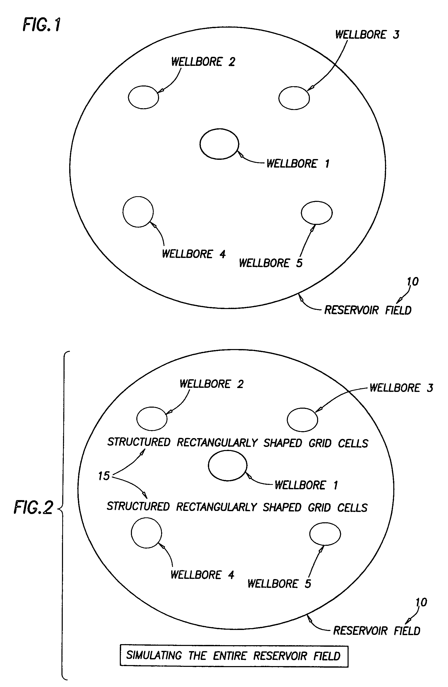
[0033]Referring to FIG. 1, a wellbore reservoir field 10 is illustrated. The reservoir field 10 includes a plurality of wellbores including wellbore 1, wellbore 2, wellbore 3, wellbore 4, and wellbore 5.

[0034]Referring to FIG. 2, when simulating the entire reservoir field 10, a “structured” grid 15 which includes a plurality of rectangularly shaped grid cells are imposed on the earth formation encompassed by the reservoir field 10. During that simulation, assume that the earth formation located near “wellbore 1” of the reservoir field 10 exhibits certain peculiar characteristics (such as water cut breakthrough—producing a lot of water instead of oil); however, the earth formation located near the other wellbores of the reservoir field 10 do not exhibit these peculiar characteristics. When modeling the entire reservoir field 10 by using the structured grid 15 of FIG. 2, the peculiar characteristics of the earth formation near that one particular wellbore (i.e., wellbore 1) may not be...


PUM


Abstract

A “near wellbore modeling” software will, when executed by a processor of a computer, model a localized area of a reservoir field which surrounds and is located near a specific wellbore in the reservoir field by performing the following functions: (1) receive input data representative of a reservoir field containing a plurality of wellbores, (2) establish a boundary around one specific wellbore in the reservoir field which will be individually modeled and simulated, (3) impose an “fine scale” unstructured grid inside the boundary consisting of a plurality of tetrahedrally shaped grid cells and further impose a fine scale structured grid about the perforated sections of the specific wellbore, (4) determine a plurality of fluxes / pressure values at the boundary, the fluxes / pressure values representing characteristics of the reservoir field located outside the boundary, (5) establish one or more properties for each tetrahedral cell of the unstructured grid and each cylindrical grid cell of the structured grid, (6) run a simulation, using the fluxes / pressure values at the boundary to mimic the reservoir field outside the boundary and using the fine scale grid inside the boundary, to thereby determine a plurality of simulation results corresponding, respectively, to the plurality of grid cells located inside the boundary, the plurality of simulation results being representative of a set of characteristics of the reservoir field located inside the boundary, (7) display the plurality of simulation results which characterize the reservoir field located inside the boundary, and (8) reintegrate by coarsening the grid inside the boundary, imposing a structured grid outside the boundary, and re-running a simulation of the entire reservoir field.

Description

CROSS REFERENCE TO RELATED APPLICATIONS[0001]This is a Utility application of prior pending U.S. provisional patent application Ser. No. 60 / 084,018 filed May 4, 1998 and entitled “Near Wellbore Modeling”.BACKGROUND OF THE INVENTION[0002]The subject matter of the present invention relates to a Near Wellbore Modeling method and apparatus adapted for use in connection with a workstation computer for modeling a single wellbore of a reservoir field in much greater detail during the modeling of a plurality of wellbores of the reservoir field for the purpose of determining the special characteristics of that single wellbore.[0003]There is a growing need in the marketplace for an improved simulation tool for the modeling of individual wellbores. In some cases, individual wellbores are ceasing to produce at very low watercuts. This is believed to be the result of a subtle near wellbore effect and laboratory work is needed to characterize the processes involved at that wellbore. However, ther...

Claims


Application Information

Patent Timeline
Patent Type & Authority Patents(United States)
IPC IPC(8): G06F17/50G01V1/18E21B49/00
CPCE21B49/00
Inventor EDWARDS, DAVID A.HOLMES, JONATHAN A.FITZPATRICK, ANTHONY J.
Owner SCHLUMBERGER TECH CORP
Why Eureka
Try Eureka