Method and apparatus for generating an OPC segmentation based on modeled intensity gradients

a technology of intensity gradient and intensity gradient, which is applied in the direction of photomechanical equipment, instruments, originals for photomechanical treatment, etc., can solve the problems of data volume explosion, unfavorable data volume maintenance, and progressively harder to deal with optical effects that arise, so as to maintain or reduce data volume, maintain correction accuracy, and “cost-effective” shape

Active Publication Date: 2008-11-11
SYNOPSYS INC
View PDF11 Cites 19 Cited by
  • Summary
  • Abstract
  • Description
  • Claims
  • Application Information

AI Technical Summary

Benefits of technology

[0009]One embodiment of the invention provides a system that facilitates dissecting a layout of an integrated circuit based on modeled intensity gradients to produce a segmentation for an optical proximity correction (OPC) process. During operation, the system performs a model-based simulation on the layout to generate intensity gradients along edges of features in the layout. The system also generates a segmentation for edges in the layout based upon the intensity gradients, wherein the segmentation is used by a subsequent OPC process in generating corrections for the layout.
[0015]In a further variation, the system determines the gradient for the given minimum-sized segment by performing a model-based simulation at two points along a normal to the segment to determine a normal component of the gradient. Note that the gradient may also be determined through other methods. For example, a numerical gradient could be used that produces an instantaneous gradient rather than the average gradient. This has the advantage of only requiring one model evaluation per segment, so it is computationally cheaper.
[0018]Therefore, rather than placing small segments everywhere on the mask, the above-described process uses gradient information to place small segments only where required. Medium-length and longer-length segments are placed in regions where the process already has adequate margin. This placement allows the difficult correction areas to use shorter segments while maintaining or reducing data volume by using longer segments in simpler areas.
[0019]The above-described technique leverages pre-correction process simulation to predict the most “cost-effective” shape for a feature. With simulated pattern characteristics and with consideration of potential mask rule violations, the method can establish an optimum correction shape “format.” For example, the choice between various line-end-treatments can be determined up front, thus focusing the OPC computation on the most effective and least complex shape, and dispensing with the need to perform post-OPC mask constraint shape adjustments. This implementation of this methodology leads to a more frugal correction that maintains correction accuracy while reducing mask construction complexity.

Problems solved by technology

As integration densities on a semiconductor chips continue to increase at an exponential rate, it is becoming progressively harder to deal with optical effects that arise during the optical lithography process involved in manufacturing the semiconductor chips.
These optical effects can cause unwanted distortions in the printed layout that is generated by the optical lithography process.
This approach leads to correction improvements, but also leads to data volume explosion and increases mask construction difficulties.
These construction difficulties can lead to masks that cannot be inspected, and sometimes not even constructed.
These mask construction issues effectively prevent the use of the very short segments necessary to make high-precision corrections.

Method used


Image

  • Method and apparatus for generating an OPC segmentation based on modeled intensity gradients
  • Method and apparatus for generating an OPC segmentation based on modeled intensity gradients
  • Method and apparatus for generating an OPC segmentation based on modeled intensity gradients

Examples


Embodiment Construction

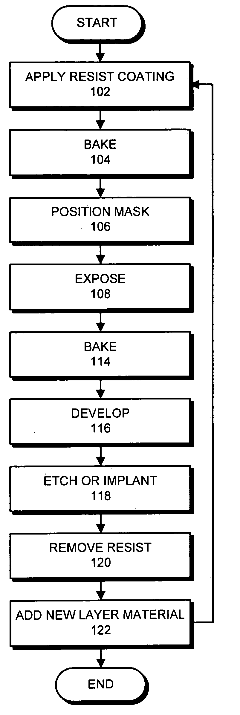
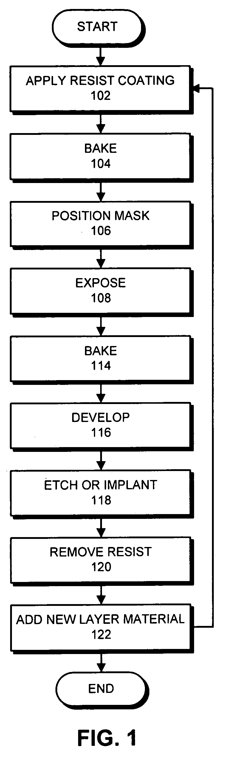
[0034]The masks described in this specification are used during the process of manufacturing an integrated circuit. More specifically, FIG. 1 presents a flow chart illustrating the wafer fabrication process in accordance with an embodiment of the invention. The system starts by applying a photoresist layer to the top surface of a wafer (step 102). Next, the system bakes the photoresist layer (step 104). The system then positions a mask over the photoresist layer (step 106), and exposes the photoresist layer through the mask (step 108). In some embodiments, multiple masks and / or exposures may be used in steps 106 and 108. Next, the system optionally bakes the wafer again (step 114) before developing the photoresist layer (step 116). Next, either a chemical etching or ion implantation step takes place (step 118) before the photoresist layer is removed (step 120). (Note that in the case of a lift-off process, a deposition can take place.) Finally, a new layer of material can be added a...


PUM

PropertyMeasurementUnit
wavelengthaaaaaaaaaa

Abstract

One embodiment of the invention provides a system that dissects edges of a layout of an integrated circuit to produce a segmentation of the layout for a subsequent optical proximity correction (OPC) operation. In order to perform the dissection, the system first performs a model-based simulation on the layout to generate intensity gradients along edges of features in the layout. Next, the system generates a segmentation for edges in the layout based upon the intensity gradients. This segmentation is used during a subsequent optical proximity correction (OPC) process to generate corrections for the layout so that the layout prints more accurately on a semiconductor chip.

Description

BACKGROUND[0001]1. Field of the Invention[0002]The invention relates to the process of designing and fabricating semiconductor chips. More specifically, the invention relates to a method and an apparatus for generating an optical proximity correction (OPC) segmentation based on modeled intensity gradients, wherein the OPC segmentation is used by an OPC process to generate corrections for the layout of an integrated circuit so that the layout prints more accurately on a semiconductor chip.[0003]2. Related Art[0004]As integration densities on a semiconductor chips continue to increase at an exponential rate, it is becoming progressively harder to deal with optical effects that arise during the optical lithography process involved in manufacturing the semiconductor chips. These optical effects can cause unwanted distortions in the printed layout that is generated by the optical lithography process.[0005]To remedy this problem, a layout is often subjected to a model-based optical proxim...

Claims


Application Information

Patent Timeline
Patent Type & Authority Patents(United States)
IPC IPC(8): G06F17/50G03F1/14G03F7/20
CPCG03F1/144G03F1/36G03F7/70441
Inventor MELVIN, III, LAWRENCE S.
Owner SYNOPSYS INC
Why Eureka
Try Eureka