Rate matching device and method for a data communication system

a data communication system and rate matching technology, applied in the direction of coding, error correction/detection using convolutional codes, instruments, etc., can solve the problems of difficult to use the rate matching device of fig. 1 when a turbo code, and the channel encoded symbols are not good, so as to improve the system performance in the data communication system and increase the efficiency of data transmission

Inactive Publication Date: 2008-11-11
SAMSUNG ELECTRONICS CO LTD
View PDF14 Cites 36 Cited by
  • Summary
  • Abstract
  • Description
  • Claims
  • Application Information

AI Technical Summary

Benefits of technology

[0014]It is further another object of the present invention to provide a device and method for rate matching channel-encoded symbols to increase the efficiency of data transmission and to improve system performance in a data communication system.

Problems solved by technology

However, when using systematic codes, such as a turbo code, there is weight between symbols, so it is not good for the channel encoded symbols that are provided to the rate matching block 120 to equally undergo puncturing or repeating.
That is, it is difficult to use the rate matching device of FIG. 1 when a turbo code is being used.
However, such a method can be used only when rate matching the turbo-encoded symbols, and cannot be used when rate matching the symbols channel-encoded with the existing convolutional codes or linear block codes.
For example, a data communication system designed to support both non-systematic code and systematic code requires two different structures in order to rate match both codes, causing an increase in complexity.

Method used


Image

  • Rate matching device and method for a data communication system
  • Rate matching device and method for a data communication system
  • Rate matching device and method for a data communication system

Examples


case 1

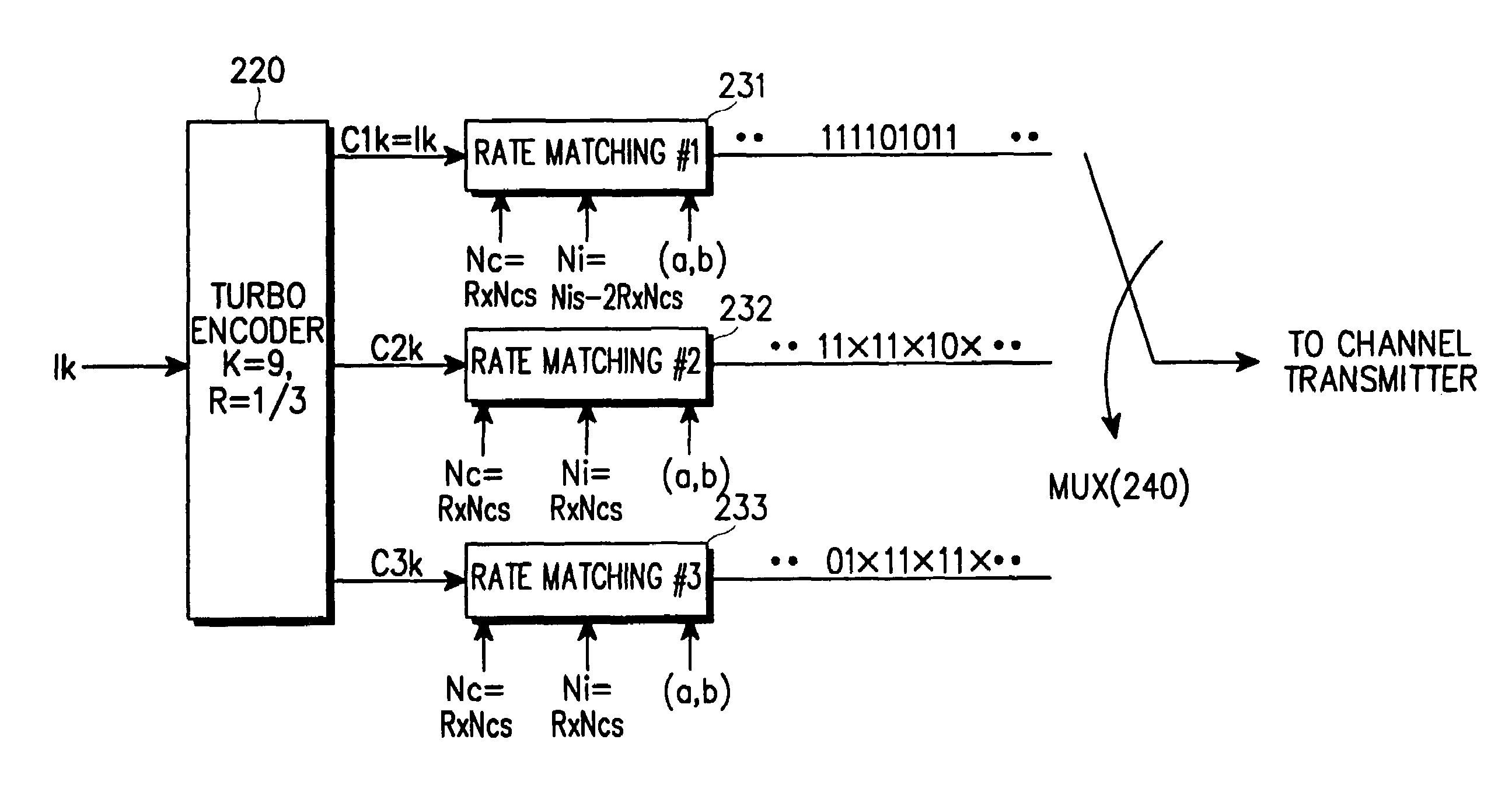
[0077, Case 2: In Case 1 and Case 2, the symbols in one frame are punctured in a uniform pattern. Specifically, in Case 1, the rate matching blocks have the same puncturing pattern because the “a” and “b” parameters are the same, and in Case 2, the rate matching blocks have different puncturing patterns because the “a” and “b” parameters are different.

case 3

[0078]In systematic puncturing, information symbols are not punctured, but the parity symbols are punctured. Here, since the puncturing pattern determining parameter values ‘a’ and ‘b’ are equal to each other, RMB2 and RMB3 perform uniform puncturing half-and-half using the same puncturing pattern.

case 4

[0079] In systematic puncturing, information symbols are not punctured, and the parity symbols are punctured. Here, since the puncturing pattern determining parameters ‘a’ and ‘b’ are different from each other, RMB2 and RMB3 perform uniform puncturing half-and-half using different puncturing patterns.


PUM


Abstract

A device and method for rate matching channel-encoded symbols in a data communication system. The rate matching device and method can be applied to a data communication system which uses one or both of a non-systematic code (such as a convolutional code or a linear block code) and a systematic code (such as a turbo code). In one aspect, the rate matching device includes a plurality of rate matching blocks, the number of the rate matching blocks being equal to a reciprocal of a coding rate of a channel encoder. The rate matching device can rate match the symbols encoded with a non-systematic code or the symbols encoded with a systematic code, by changing initial parameters including the number of input symbols, the number of output symbols, and the puncturing or repetition pattern determining parameters.

Description

PRIORITY[0001]This application is a continuation application of application Ser. No. 09 / 611,014, filed Jul. 6, 2000, now U.S. Pat. No. 6,751,772, which claims priority to an application entitled “Rate Matching Device and Method for Data Communication System” filed in the Korean Industrial Property Office on Jul. 6, 1999 and assigned Ser. No. 99-26978, and an application entitled “Rate Matching Device and Method for Data Communication System” filed in the Korean Industrial Property Office on Jul. 10, 1999 and assigned Ser. No. 99- 27865, the contents of each of which are incorporated herein by reference.BACKGROUND OF THE INVENTION[0002]1. Field of the Invention[0003]The present invention relates generally to a channel encoding device and method for a data communication system, and in particular, to a device and method for rate matching of channel-encoded symbols.[0004]2. Description of the Related Art[0005]Generally, in digital communication systems such as satellite systems, ISDN (I...

Claims


Application Information

Patent Timeline
Patent Type & Authority Patents(United States)
IPC IPC(8): H03M13/03G06F11/00H03M13/00G06F11/10H03M13/05H03M13/23H03M13/29H04L1/00H04L1/08H04L12/20
CPCH03M13/2957H03M13/2993H03M13/6356H03M13/6362H04L1/08H04L1/0041H04L1/0059H04L1/0066H04L1/0069H03M13/6569H04L1/0013H03M13/6513
Inventor KIM, MIN-GOOKIM, BEONG-JOKIM, SE-HYOUNGCHOI, SOON-JAELEE, YOUNG-HWAN
Owner SAMSUNG ELECTRONICS CO LTD
Why Eureka
Try Eureka