Roof fascia with extension cleat

a technology of roof fascia and extension cleat, which is applied in the direction of roof tools, snow traps, roofs, etc., can solve the problems of cover plate damage, and achieve the effect of prolonging the overall length of the edging system

Inactive Publication Date: 2008-11-18
METAL ERA LLC
View PDF24 Cites 41 Cited by
  • Summary
  • Abstract
  • Description
  • Claims
  • Application Information

AI Technical Summary

Benefits of technology

[0010]It is an object of the present invention to provide a roof edging system which includes an anchor bar or base plate, and further includes an extension cleat attachable to the anchor bar to thereby extend the overall length of the edging system as necessary.

Problems solved by technology

However, with roof edging or fascia systems of this type, the size and shape of the cover plate that is attached to the base plate is determined solely by the size of the base plate, i.e., a small base plate can only be used with a small cover plate.
Therefore, if a particular edging system is used for a building, the size of the cover plate utilized with the system has to conform in size to the size of the base plate and cannot be varied in size, often resulting in a situation where the edging system provides an appearance to the roof of the building which does not conform to the remainder of the building.
The thinness of the material forming the cover plates often times results in damage being done to the cover plates both during the installation of the cover plates and during the exposure of the cover plates to the elements.

Method used


Image

  • Roof fascia with extension cleat
  • Roof fascia with extension cleat
  • Roof fascia with extension cleat

Examples


first embodiment

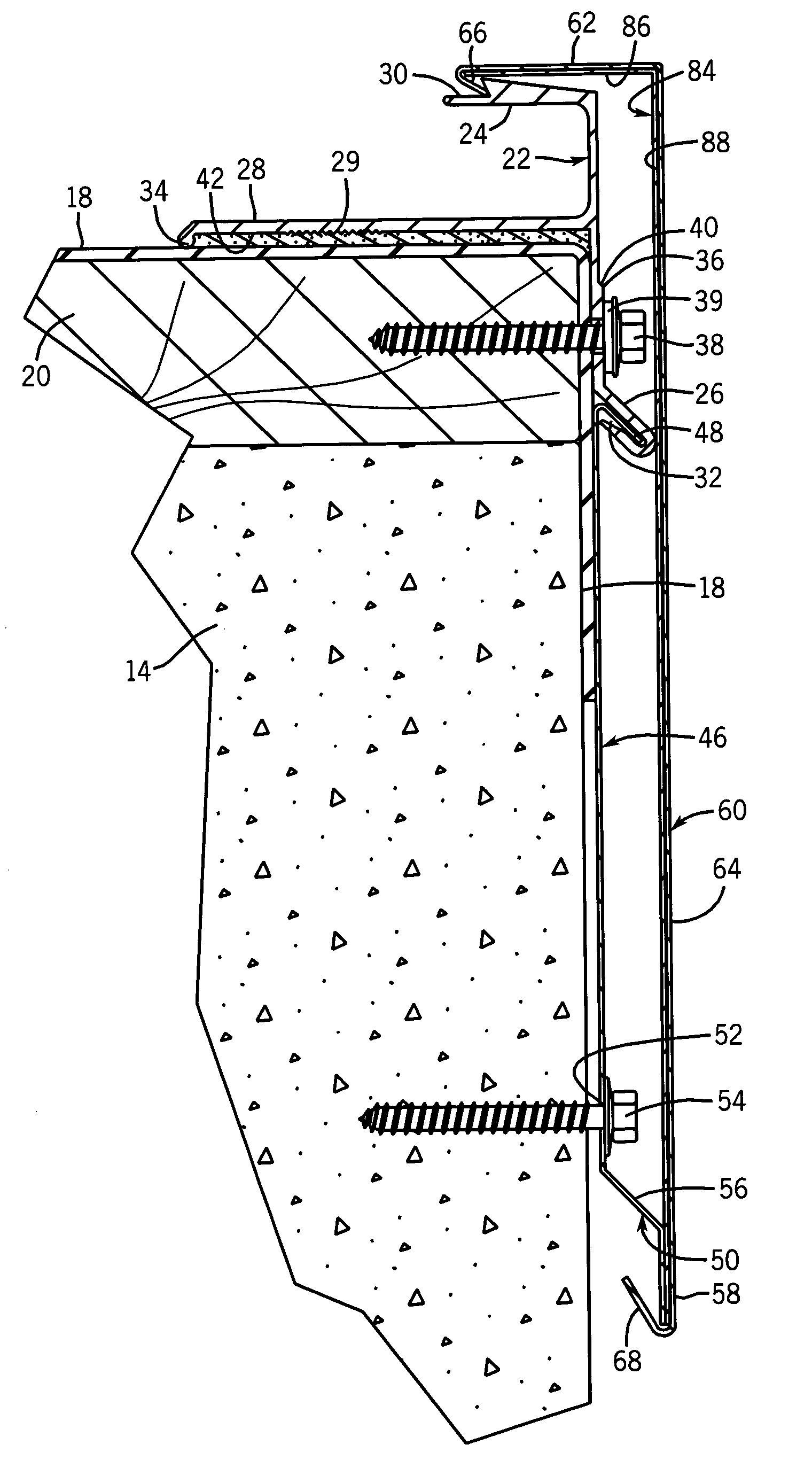
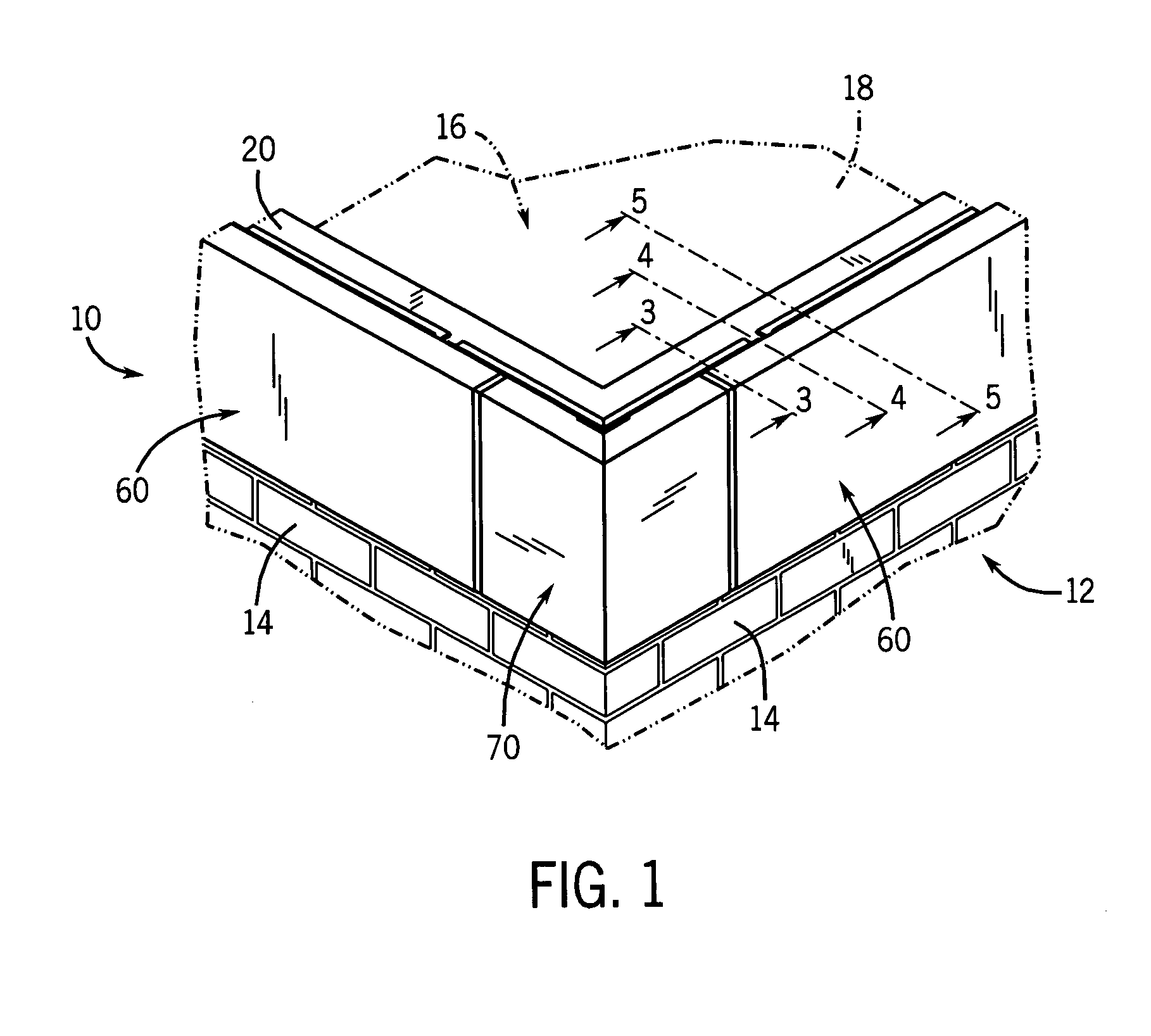
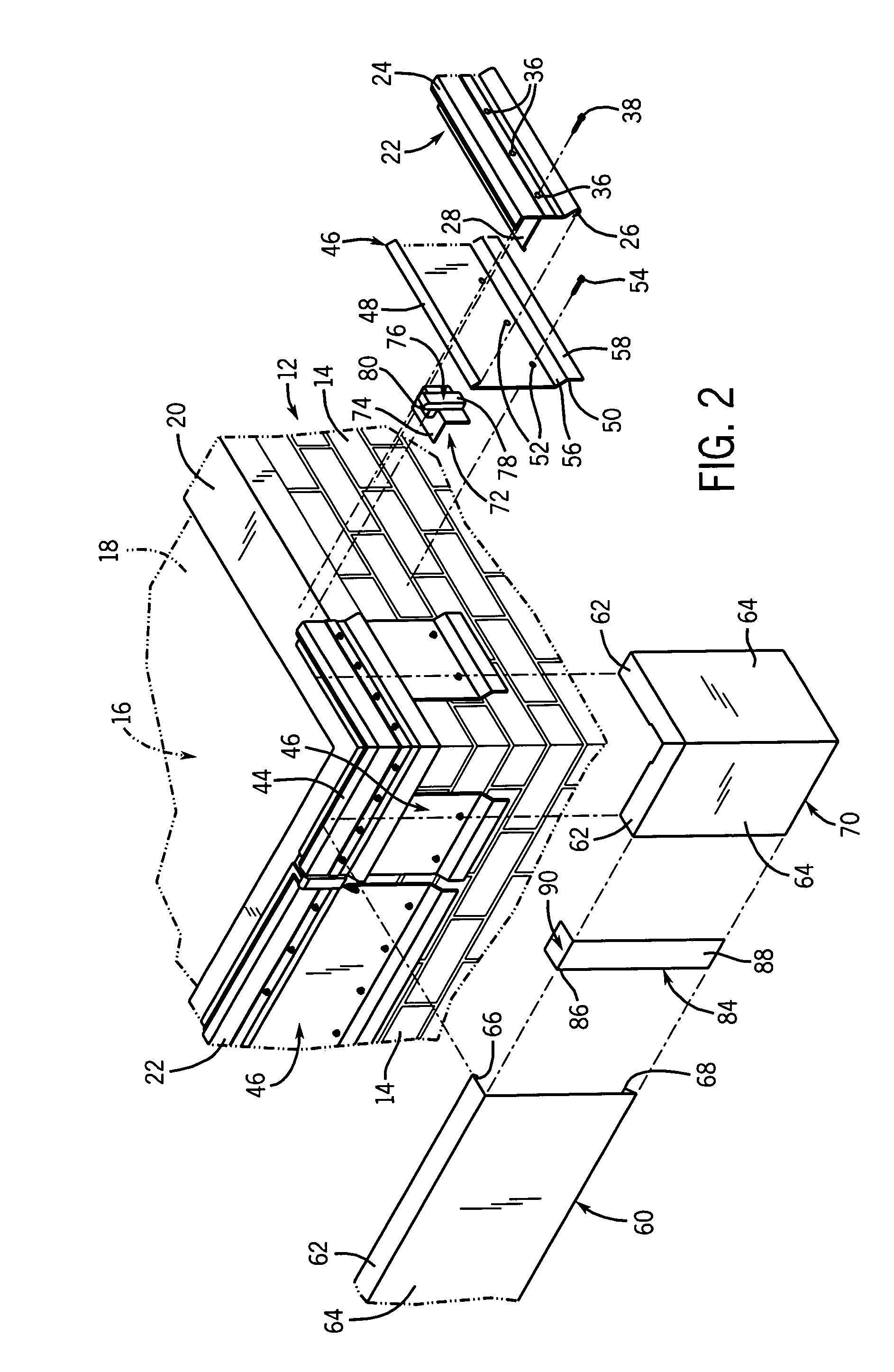
[0031]As best shown in FIGS. 2-5, in a first embodiment the system 10 is attached to the building 12 having a built up or modified roof over a roofing membrane 18 that covers the roof 16 and extends upwardly from the roof 16 over a conventional wooden nailer 20 positioned on top of each of the walls 14. The membrane 18 extends over the nailer 20 and downwardly to cover the uppermost portion of each of the walls 14 and provide a waterproof layer over the entire surface of the roof 16 of the building 12. Further, in some roof constructions, there is also a flashing strip (not shown) and / or base sheet (not shown) used in conjunction with the membrane 18.

[0032]The edging system 10 includes an anchor bar 22 formed of a rigid material, preferably metal, and most preferably aluminum. The anchor bar 22 is formed as an elongate generally rectangular member having an engagement portion 24 extending perpendicularly from one end of the anchor bar 22, a locking flange 26 extending outwardly from...

second embodiment

[0046]Referring now to FIG. 6, the edging system 10 of the present invention for use with standard flat roof constructions is illustrated. In this embodiment, the anchor bar 22 includes a sealing flange 92 that has a length approximately equal to the length of the engagement portion 24. The sealing flange 92 includes a bead 94 opposite the anchor bar 22 that protrudes upwardly from the sealing flange 92, allowing a non-curing sealant 95 positioned beneath the flange 92 to be exposed. The non-curing sealant 95 can be any suitable sealant. In this embodiment, the extension cleat 46 and cover plate 60 are secured to the anchor bar 22 in the same manner as the previous embodiment.

[0047]A third embodiment of the edging system 10 of the present invention is illustrated in FIG. 7. In this embodiment, the anchor bar 22 has the sealing flange is essentially combined with the cover engagement portion 24. Thus, in this embodiment, there is only one rearwardly extending flange on the anchor bar...

fourth embodiment

[0048]the edging system 10 of the present invention is illustrated in FIG. 8. In this embodiment, the anchor bar 22 is adapted for use with a cover plate 97 that forms a coping for a wall 14 of the building 12. In this embodiment, the anchor bar 22 includes a modified engagement portion 98, a shortened sealing flange 100, apertures 36, and locking flange 26. The modified engagement portion 98 is integrally formed with the anchor bar 22 and includes an outwardly extending portion 102 and a downwardly sloping portion 104 disposed on opposite sides of the anchor bar 22 opposite the locking flange 26.

[0049]A groove 106 is defined between the downwardly sloping portion 104 and the anchor bar 22, and receives one end of an anchor plate 108. The anchor plate 108 is formed of a generally rigid material, such as a metal, and includes an upwardly extending portion 110 at one end which is received within the groove 106. Opposite the groove 106, the portion 110 is connected with an L-shaped cen...


PUM


Abstract

A roof edging system includes an anchor bar, an extension cleat attachable to the anchor bar, and a cover plate applied over the anchor bar and extension cleat. The anchor bar may be of a generally uniform size and shape and the extension cleat may be of varying sizes. The anchor bar and extension cleat are secured to the exterior of the building using fasteners inserted through a number of apertures in each member. The engagement of the anchor bar with the roof provides a waterproof seal between a roofing membrane placed on the roof and the anchor bar. The extension cleat provides a means to vary the overall length of the assembly. A durable cover plate may then be attached over the anchor bar and extension cleat to provide an aesthetically pleasing appearance to the periphery of the roof of the building.

Description

RELATED APPLICATIONS[0001]This application is a continuation-in-part of application Ser. No. 10 / 277,552 filed on Oct. 22, 2002, which has been allowed and patented as U.S. Pat. No. 6,912,814.BACKGROUND OF THE INVENTION[0002]1. Field of the Invention[0003]The present invention relates to roof edging and waterproofing systems, and more specifically to a roof edging system capable of being adapted for use with facings of various sizes to provide the desired appearance for roof edges of buildings.[0004]2. Background of the Invention[0005]Many types of buildings have flat roofs with exposed roof edges that must be sealed in order to prevent water from leaking into the interior of the building. The roofs on buildings of this type include fully adhered or mechanically attached single ply roofs and built-up or modified roof systems, among others.[0006]In order to effectively seal the roofs of these buildings, many different roof edging systems, such as fascias and copings, have been develop...

Claims


Application Information

Patent Timeline
Patent Type & Authority Patents(United States)
IPC IPC(8): E04D13/15E04D3/38
CPCE04D3/405E04D13/15E04D13/155
Inventor INZEO, JOSEPH A.KITTILSTAD, SCOTT A.
Owner METAL ERA LLC
Why Eureka
Try Eureka