Microfluidic device with dep arrays

a microfluidic device and array technology, applied in fluid controllers, solid separation, laboratories, etc., can solve the problems of unreliable diagnostics, multiple dep electrode arrays, and high power requirements for implementing microfluidic devices. , to achieve the effect of increasing the cost and size of the devi

Pending Publication Date: 2022-02-10
QUANTUMDX GROUP
View PDF0 Cites 0 Cited by
  • Summary
  • Abstract
  • Description
  • Claims
  • Application Information

AI Technical Summary

Benefits of technology

[0033]By virtue of this recognition, microfluidic devices can be provided that comprise multiple DEP electrode arrays, arranged for example in parallel and, advantageously powered from a single set of connection points, without the consistency of the operation of the DEP electrode arrays falling below a

Problems solved by technology

Unfortunately, when attempting to implement a DEP-based particle manipulation system in a microfluidic device comprising multiple parallel processing channels, a number of technical issues arise.
Devices comprising multiple DEP electrode arrays, whilst necessary for commercial implementation, are nevertheless difficult to implement because variances within the device tend to result in the DEP electrode arrays performing differently from each other (e.g. capturing target particles at inconsistent rates).
Beyond a certain tolerance level, such differences in performance can lead to unreliable d

Method used


Image

  • Microfluidic device with dep arrays
  • Microfluidic device with dep arrays
  • Microfluidic device with dep arrays

Examples


Embodiment Construction

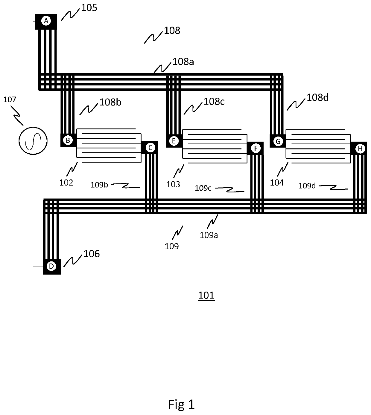
[0042]FIG. 1 provides a simplified schematic diagram of an arrangement for supplying an alternating current to a plurality of electrode arrays for use in a microfluidic device for selectively capturing target particles using dielectrophoresis (DEP). The examples described use positive DEP (pDEP).

[0043]The arrangement 101 comprises a first electrode array 102, second electrode array 103 and third electrode array 104. Each electrode array comprises an interdigitated electrode (IDE) array. In a typical implementation, more electrode arrays may be used (for example 32 parallel channels each with its own electrode array—each channel being 2 mm in width—gives an appropriate footprint for a POC device), but for clarity only three are shown in FIG. 1.

[0044]Whilst the figures show a linear interdigitated electrode array, it would be understood that arrays of differing physical conformations could be used, for example interdigitated spiral electrodes could be used.

[0045]The first, second and ...


PUM


Abstract

Microfluidic device having a plurality of microfluidic channels and corresponding dielectrophoresis (DEP) electrode arrays, each channel arranged to direct fluid over a DEP electrode array such that in use target particles are manipulated by the DEP electrode array. The device also has a first connection point and second connection point for connecting the device to an alternating current source, a first input of each DEP electrode array connected to the first connection point via the first conductor and second input of each DEP electrode array connected to the second connection point via the second conductor. A resistance of the first conductor between the first input of each electrode and the first connection point, and a resistance of the second conductor between the second input of each electrode and the second connection point is substantially at least an order of magnitude less than a total resistance of the connected electrode arrays.

Description

TECHNICAL FIELD[0001]The present invention relates to microfluidic devices, and microfluidic devices that use dielectrophoresis (DEP) to selectively manipulate target particles.BACKGROUND[0002]Dielectrophoresis (DEP) is a well-known phenomenon that can be used to selectively move and / or manipulate particles based on the dielectric properties of the particles. The particle will move either in the direction of a field gradient (positive DEP) or in the opposite direction (negative DEP).[0003]In particular, a DEP array (comprising for example an interdigitated electrode array) can be adapted, based on its geometry and the voltage and frequency of an electrical power source connected to the array, to selectively manipulate certain specific particles from a fluid being passed over the DEP array.[0004]In principle, DEP provides a promising particle selection mechanism for microfluidic diagnostic applications where, for example, fluid samples are processed to identify and analyse fluid-born...

Claims


Application Information

Patent Timeline
IPC IPC(8): B01L3/00
CPCB01L3/502761B01L2200/025B01L2200/027B01L2400/0424B01L2200/0647B01L2300/0819B01L2300/12B01L2200/04B01L2300/0816B01L2300/0645B01L2200/0668B01L2200/12B03C2201/26B03C5/005B03C5/026B01L3/5027B01L3/502715
Inventor MURTON, HEATHERSCHMID, LOTHARBOADA, EDUARDO
Owner QUANTUMDX GROUP
Why Eureka
Try Eureka