Lighting device, liquid crystal display device, and electronic apparatus

a liquid crystal display and light source technology, applied in the direction of static indicating devices, lighting and heating devices, instruments, etc., can solve the problems of liquid crystal display devices having a usability problem, and it is difficult to read the display from a direction deviating from the viewing angl

Active Publication Date: 2008-11-18
BOE TECH GRP CO LTD
View PDF17 Cites 26 Cited by
  • Summary
  • Abstract
  • Description
  • Claims
  • Application Information

AI Technical Summary

Benefits of technology

[0007]An advantage of the present invention is that it provides a lighting device in which the exit angle of emitted light can be changed.
[0008]Another advantage of the invention is that it provides an electro-optical device and an electronic apparatus in which the range of a viewing angle can be varied.
[0009]A lighting device of the invention includes: a plurality of light sources; and an optical waveguide, wherein light emitted from the plurality of light sources is incident from a side of the optical waveguide and then emitted from one main plane of the optical waveguide, wherein the optical waveguide includes a first inclined plane for reflecting light emitted from a first light source and then emitting the light from the one main plane, and a second inclined plane for reflecting light emitted from a second light source and then emitting the light from the one main plane at an exit angle different from the light emitted from the first light source, and wherein each of the light sources is independently driven.
[0010]According to this configuration, since each of the light sources is independently driven, the exit angle of the emitted light can be changed.
[0011]Further, it is preferable that the plurality of light sources are respectively disposed at different corners of the optical waveguide.
[0012]According to this configuration, since light can be incident on the entire optical waveguide, a dead angle region can be prevent when light is incident on the optical waveguide. It is thus possible to provide a compact lighting device in which light irregularities do not occur.

Problems solved by technology

However, because the above-mentioned mobile devices are widely used in public places, many mobile device users are frequently concerned about revealing their personal information, etc. to others while using it.
On the other hand, because the liquid crystal display devices generally have a narrow viewing angle, it is difficult to read the display from a direction deviating from the viewing angle.
Therefore, liquid crystal display devices have a usability problem.

Method used


Image

  • Lighting device, liquid crystal display device, and electronic apparatus
  • Lighting device, liquid crystal display device, and electronic apparatus
  • Lighting device, liquid crystal display device, and electronic apparatus

Examples


first embodiment

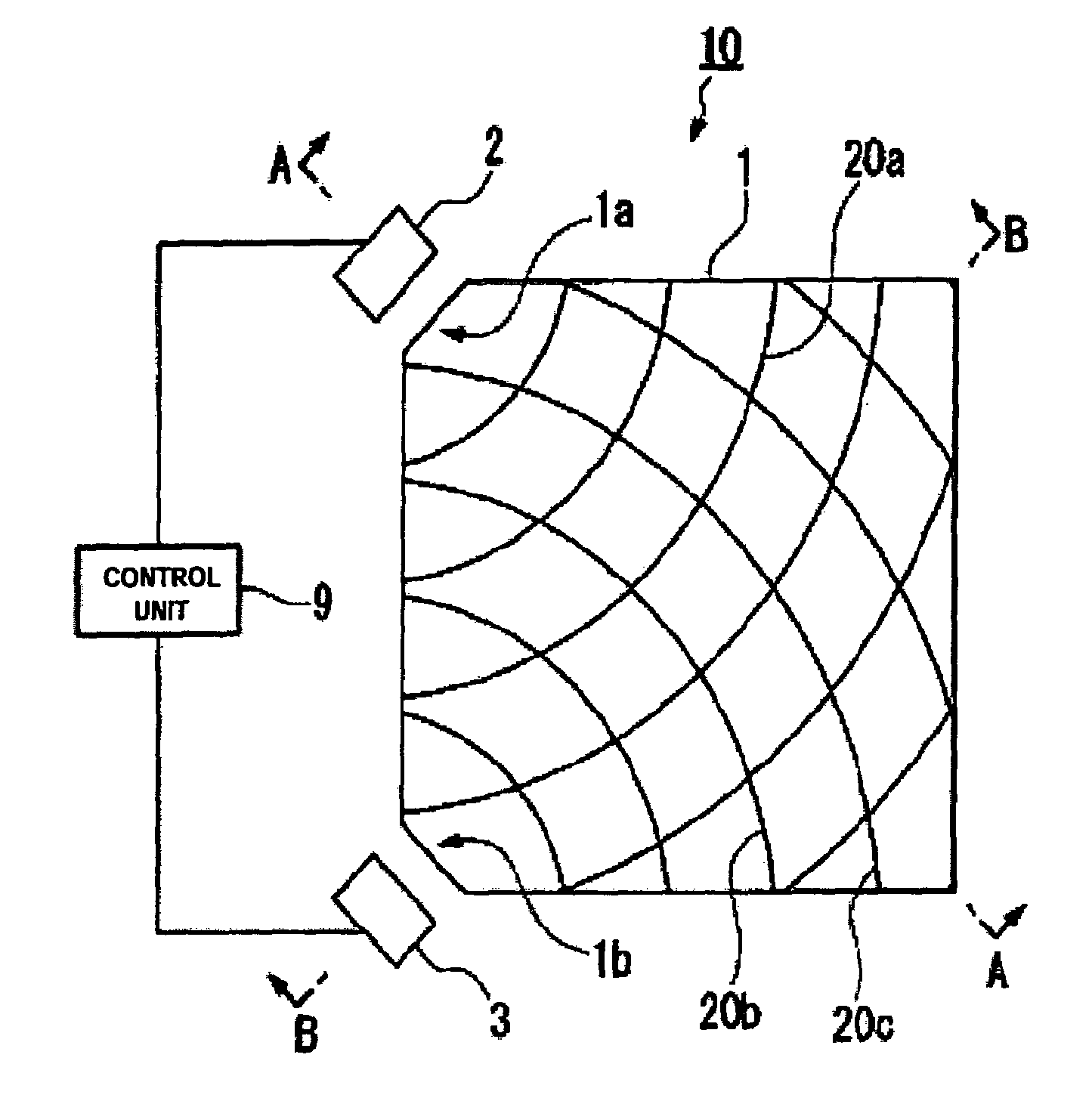
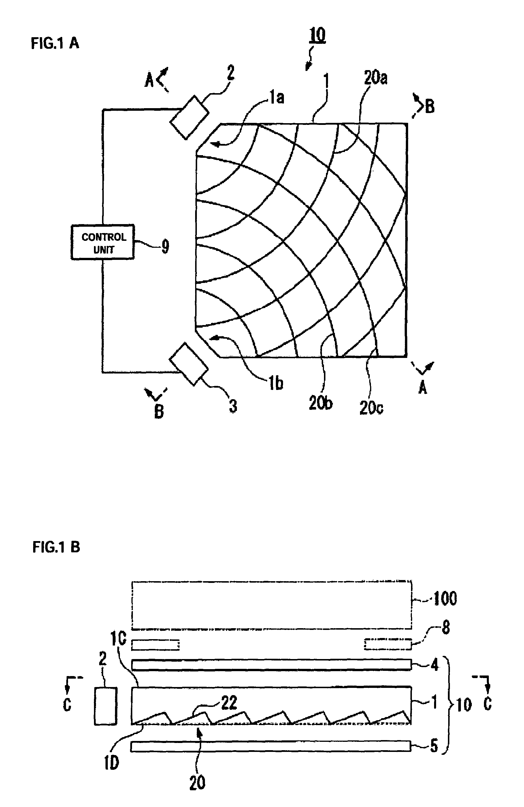
[0042]FIGS. 1A and 1B are explanatory diagrams illustrating a lighting device according to a first embodiment of the invention. The lighting device 10 according to the embodiment mainly includes an optical waveguide 1 having a rectangular flat plate shape, a first light source 2 and a second light source 3 both of which are disposed in opposite to corners of the optical waveguide 1, a reflective sheet 5 disposed on a rear surface of the optical waveguide 1, and a diffuser sheet 4 disposed on a front surface of the optical waveguide 1.

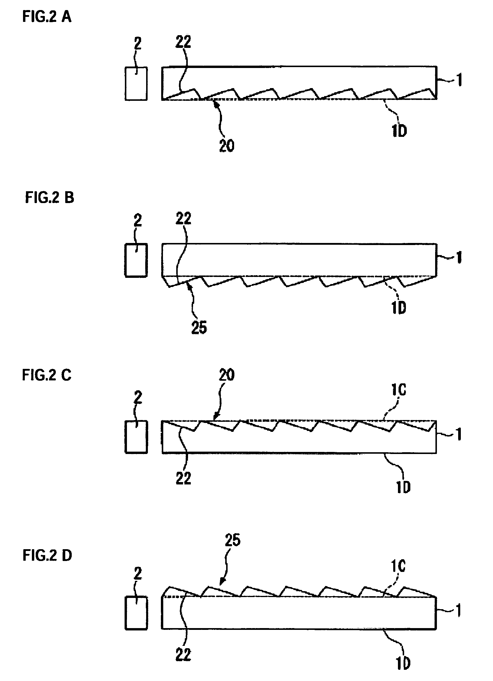
[0043]FIG. 1A is a plan view of the lighting device according to a first embodiment of the invention, which is a cross-sectional view of the lighting device taken along line C-C of FIG. 1B. The lighting device 10 of the embodiment includes the optical waveguide 1 of a rectangular flat panel shape. The optical waveguide 1 is formed about 0.6 mm in thickness using a light-transmissive material such as an acrylic resin. Further, longitudinal corners 1A and...

second embodiment

[0061]FIG. 5 is an explanatory diagram illustrating a lighting device according to a second embodiment of the invention. The lighting device of the second embodiment is different from that of the first embodiment in which the diffuser sheet is disposed on the front surface 1C of the optical waveguide 1, in that a prism sheet 6 having indentations and protrusions is disposed at a side opposite to the front surface 1C of the optical waveguide 1. Furthermore, the shape of grooves formed in the optical waveguide 1 is different from those of the first embodiment. Moreover, the same reference numerals indicate the same components as those of the first embodiment, and detailed description thereof will be omitted.

[0062]In the second embodiment, the prism sheet 6 is disposed on the front surface 1C of the optical waveguide 1, as shown in FIG. 5. The prism sheet 6 includes a plurality of prisms 7 having a tripod pillar shape or a square pillar shape, which are formed by using a light-transmis...


PUM

PropertyMeasurementUnit
vertex angleaaaaaaaaaa
gradient angleaaaaaaaaaa

Abstract

A lighting device of the invention includes: a plurality of light sources; and an optical waveguide, wherein light emitted from the plurality of light sources is incident from a side of the optical waveguide and then emitted from one main plane of the optical waveguide. The optical waveguide includes a first inclined plane for reflecting light emitted from a first light source and then emitting the light from the one main plane, and a second inclined plane for reflecting light emitted from a second light source and then emitting the light from the one main plane at an exit angle different from the light emitted from the first light source, and wherein each of the light sources is independently driven.

Description

BACKGROUND OF THE INVENTION[0001]1. Technical Field[0002]The present invention relates to a lighting device, a liquid crystal display device, and an electronic apparatus.[0003]2. Related Art[0004]In recent years, liquid crystal display devices, such as liquid crystal panels, are widely installed in the image display units of various electronic apparatuses. For example, such liquid crystal display devices are suitably used in the display units of mobile devices such as mobile phones due to their slimness, low weight and low power consumption. The liquid crystal display devices mainly include a liquid crystal panel in which a liquid crystal layer is interposed between a pair of substrates, and a lighting device (backlight) disposed on the non-viewing screen side of the liquid crystal panel. Further, the orientation state of liquid crystal molecules is controlled by applying an electric field to the liquid crystal layer by transparent electrodes formed at the sides of the liquid crysta...

Claims


Application Information

Patent Timeline
Patent Type & Authority Patents(United States)
IPC IPC(8): F21V7/04F21V8/00F21Y101/02G02F1/13357G02B6/00G02F1/133
CPCG02B6/0036G02B6/0046G02B6/0073G02B6/0068G02B6/0053G02F1/1335
Inventor ONISHI, YASUNORIYAMADA, KATSUMIMASUNAGA, YASUTAKA
Owner BOE TECH GRP CO LTD
Why Eureka
Try Eureka