
Aspirating and mixing of liquids within a probe tip

Inactive Publication Date: 2008-11-18
ORTHO-CLINICAL DIAGNOSTICS
View PDF30 Cites 5 Cited by
  • Summary
  • Abstract
  • Description
  • Claims
  • Application Information

AI Technical Summary

Benefits of technology

[0016]the improvement wherein the capillary number resulting from the mixing in step c) does not exceed about 0.01, the capillary number being defined as the ratio of liquid velocity times viscosity and surface tension, so that any tails formed during the mixing step c) are minimized.
[0042]A related advantage of the aforesaid mechanical device for preventing carry-over contamination, is that it renders the tip of the invention more manufacturable.

Problems solved by technology

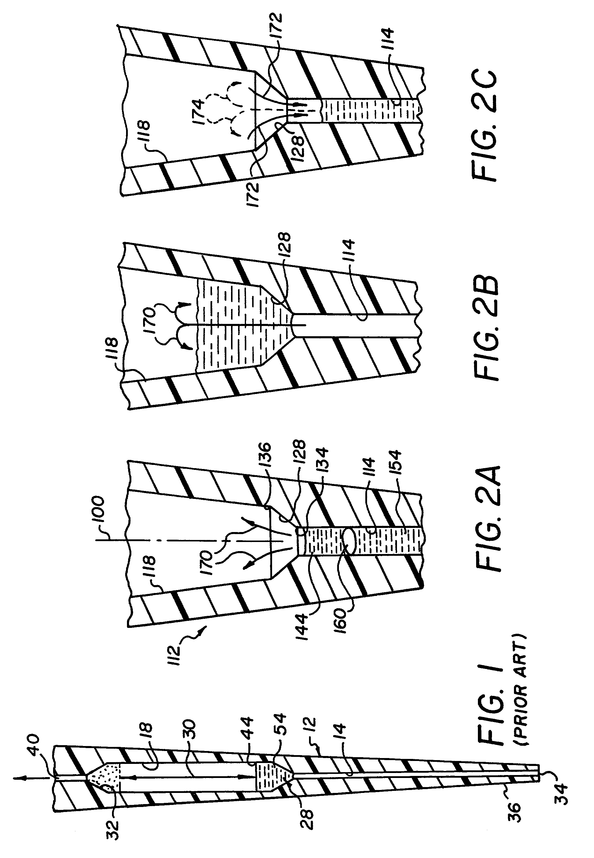
In the examples shown in U.S. Pat. No. 5,773,305, the liquids are retained in the enlarged chamber and simply sloshed back and forth in that chamber to achieve mixing. FIG. 3 thereof makes it clear that simply aspirating the liquids into the enlarged chamber past a step discontinuity created by the enlarged inside diameter, is ineffective in creating a mixture.
Although mixing can occur in such a fashion for relatively large volumes, it is not as effective for small volumes, e.g., volumes that total 100 to 600 microliters.
Such reiterations of the mix step are time-consuming, and beg for an improvement.
Furthermore, it is not the case that cross-contamination is preventable only by using such an oil shield.
Furthermore, some proteins can destroy the shield effect of the oil.
Furthermore, the '162 patent is notably deficient in any teaching to prevent cross-contamination when aspirating liquid 6 immediately after liquid 4, between the two liquids within the bulk container of liquid 6.
Although the oil shield of the '305 patent might seem to be applicable to the probe of the '162 patent as well, such a shield has disadvantages as noted above.
Yet another disadvantage of the teachings of the '162 patent is that when the two disparate liquids are moved back and forth across the boundary 15, unmixed “tails” of one or both liquids can be left behind as coatings on either the enlarged chamber or the narrower intake portion.
Such residual tails do not get mixed when the main body of liquids is moved across boundary 15, so that the tails are undesirable.

Method used


Image

  • Aspirating and mixing of liquids within a probe tip
  • Aspirating and mixing of liquids within a probe tip
  • Aspirating and mixing of liquids within a probe tip

Examples


example no.1

EXAMPLE NO. 1

[0097]A probe was constructed having two capillaries with different inner diameters. The smaller capillary had an inner diameter of 0.557 mm. The larger capillary had an inner diameter of 2.29 mm. The length of the smaller capillary was 41 mm, which holds up to 10 micro-liter of fluid. The larger capillary had a length of 30 mm.

[0098]A type B blood of 4 microliters was aspirated from the bottom end of the small capillary by the pump. The pump then continued to withdraw 1 micro-liters of air in the small capillary. 4 micro-liters of the agglutinating reagent described above was aspirated thereafter and the air bubble separated the two liquids in the smaller capillary.

[0099]The pump was then driven to move all the fluids across the transition zone between the small and large capillary with a flow rate of 0.5 micro-liter / second. Once in the larger capillary, a spherical air bubble was created by the surface tension, and the two liquids started to encounter and mix. As the ...

example 2

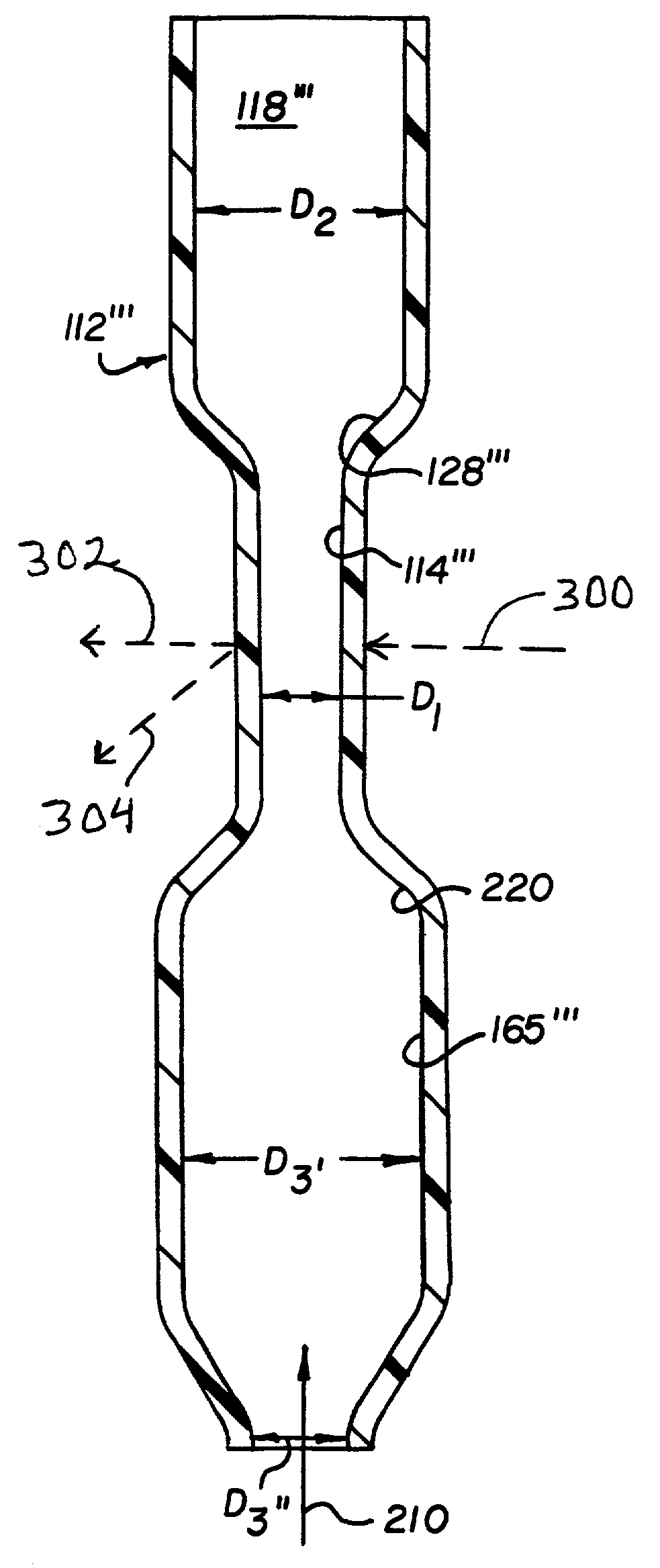
[0103]A probe was constructed similar to shown in FIG. 9, except that the tip portion 165′″ was cut off at line C-C to create a cone-shaped tip portion having an inside diameter at D3 of about 2.54 mm, and at cut line C-C of about 1 mm, with a cone angle of about 20 degrees and a length of 10 mm. Tip portion 114′″ had a length of about 15 mm and an inside diameter D1 of about 1 mm. Tip portion 118′″ had a diameter D2 of about 4.7 mm. Blood in an amount of 10 microliters was aspirated into the entire tip ensemble through cone portion 165′″, after which the cone was wiped clean. Then 10 microliters of reagent were aspirated into the tip in the same manner, producing a total liquid volume of 20 microliters. This total volume was then moved back and forth so as to proceed entirely into portion 118′″ and then entirely into portion 165′″, and so forth, until mixing was complete. This required 7.5 repetitions (cycles) at a flow rate of 50 microliters per sec. Total displacement of fluids w...


PUM

PropertyMeasurementUnit
Lengthaaaaaaaaaa
Diameteraaaaaaaaaa

Abstract

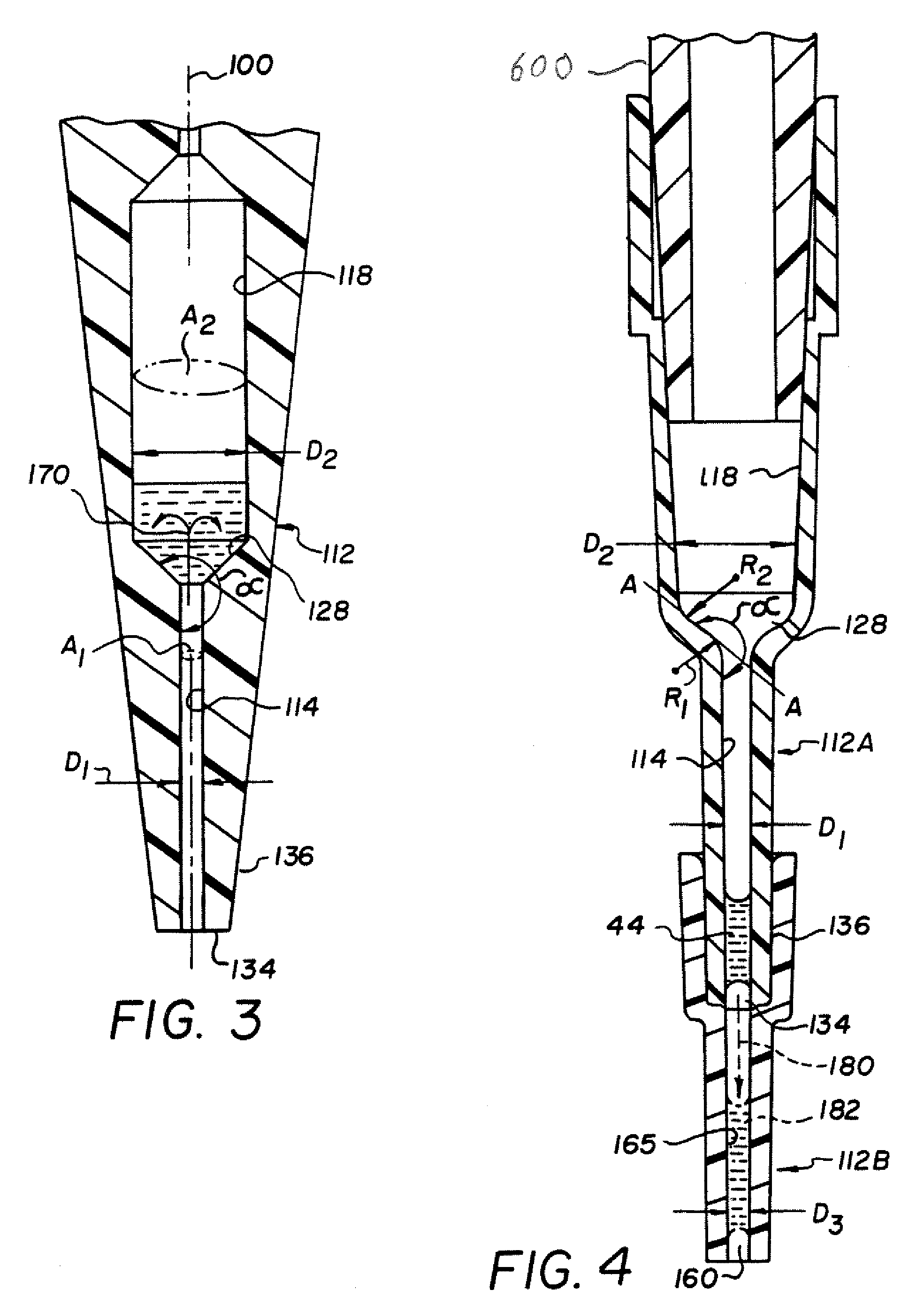
Apparatus and a method for mixing a liquid within a disposable aspirating probe tip so that most of the liquid is forced to move past a transition zone between two different inside diameters to cause rotational mixing. The apparatus and method can be used to provide agglutination of blood, which in turn can be used for blood typing. The probe tip can include a single integral piece, or two separate portions. The transition zone can include a sharp demarcation between inside diameters, or a smooth one.

Description

CROSS REFERENCE TO RELATED APPLICATIONS[0001]This application is a divisional of U.S. Ser. No. 09 / 510,928, filed Feb. 22, 2000, the contents which are hereby incorporated by reference now U.S. Pat. No. 6,641,993.FIELD OF THE INVENTION[0002]The invention relates to apparatus and a method for mixing two liquids within a tip on an aspirating probe, to ensure a reaction between the liquids.BACKGROUND OF THE INVENTION[0003]It is known from U.S. Pat. Nos. 5,773,305 and 5,114,162 to mix a fluid sample such as blood and a diluent, inside a probe tip by first aspirating both liquids into the tip, and then drawing said liquids further up into the tip into a mixing chamber having an enlarged inside diameter compared to the rest of the tip. The mixing can be achieved, for example, by reciprocating the mass of liquids up and down numerous times.[0004]In the examples shown in U.S. Pat. No. 5,773,305, the liquids are retained in the enlarged chamber and simply sloshed back and forth in that chambe...

Claims


Application Information

Patent Timeline
IPC IPC(8): B01L3/02B01F5/10B01F11/00B01F13/00G01N35/10H05K3/00H05K3/22
CPCB01F5/10B01F11/0074B01F13/00B01L3/0275G01N35/10H05K3/0097B01F11/0071Y10T436/25B01F2215/0037G01N2035/106H05K3/0052H05K3/225H05K2201/10598H05K2203/0165H05K2203/167Y10T436/25625B01F25/50B01F31/651B01F31/65B01F33/00B01F2101/23
Inventor JACOBS, MERRIT N.DING, ZHONGBROOKES, RONALD F.
Owner ORTHO-CLINICAL DIAGNOSTICS
Learn More