
System and method for utilizing magnetic energy

a technology of magnetic energy and system, applied in the direction of magnets, windings, magnetic bodies, etc., can solve the problems of increasing difficulty in releasing objects from magnets, damage to objects, and individual difficulty in prying objects from magnets, so as to improve the energy efficiency of devices or systems, and increase the magnetic field

Inactive Publication Date: 2008-11-18
HILDENBRAND JACK W
View PDF3 Cites 65 Cited by
  • Summary
  • Abstract
  • Description
  • Claims
  • Application Information

AI Technical Summary

Benefits of technology

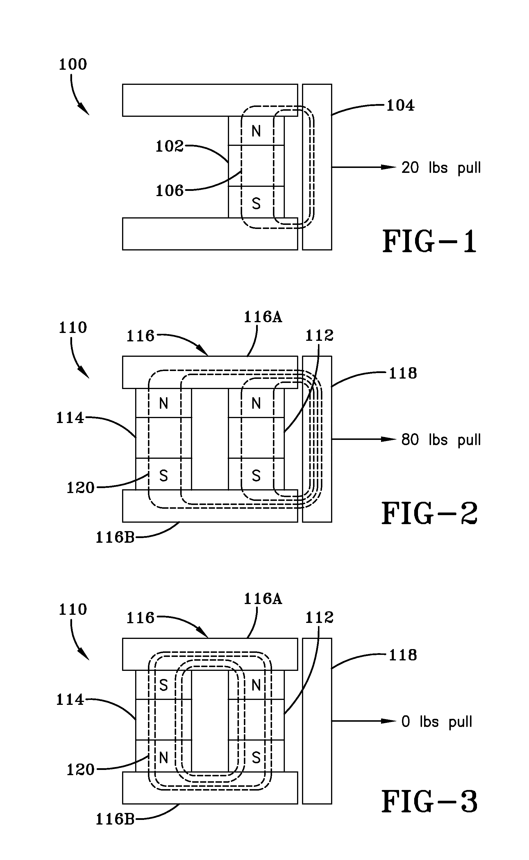
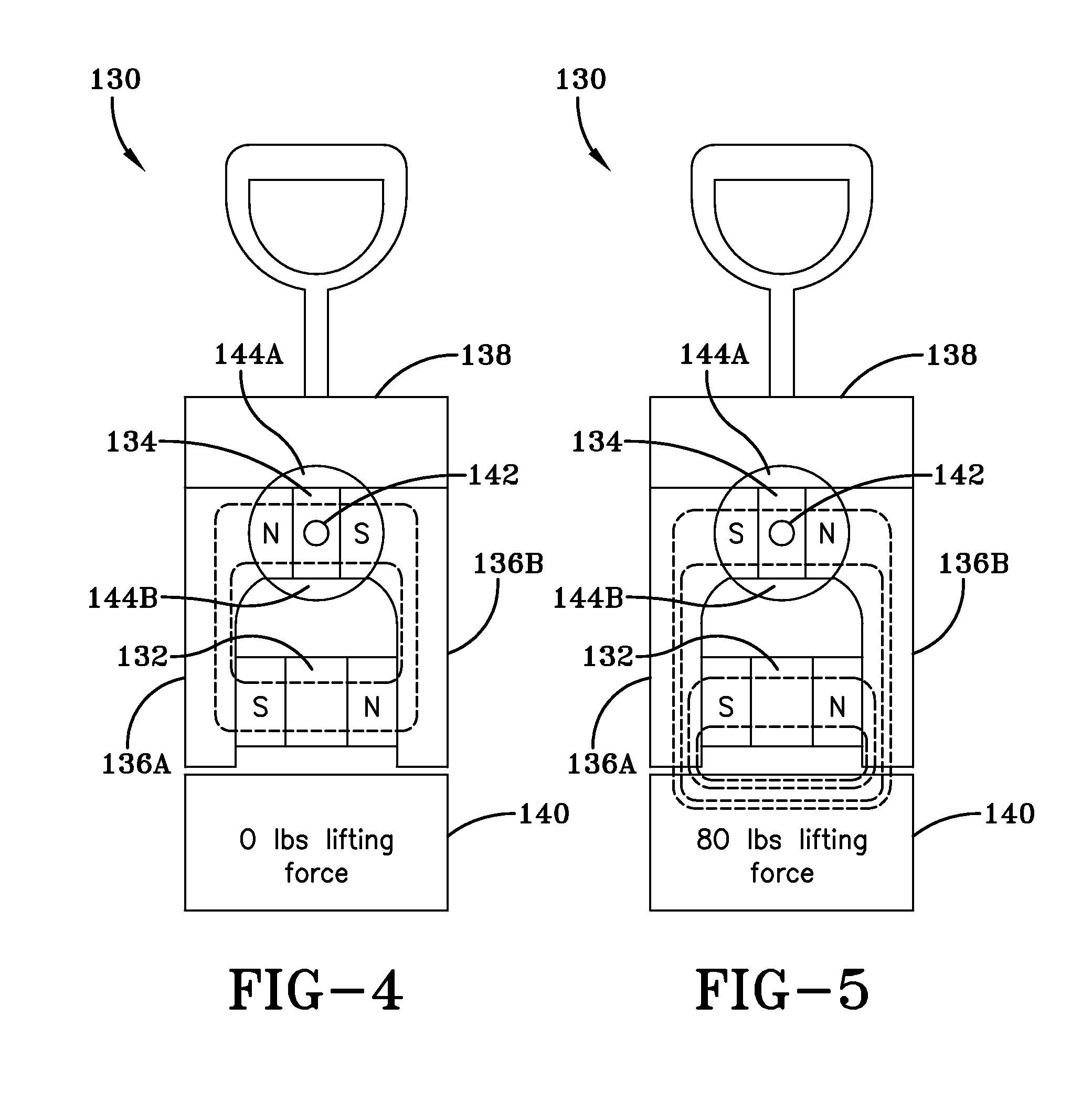
[0009]The exemplary embodiments of the present invention may be embodied in a variety of systems. For example, by redirecting or switching a magnetic field that is generated by magnets, the present invention may be used to perform a variety of functions including, but not limited to: (1) to control, manipulate, hold, and / or release a load; (2) to open and / or close a pathway; (3) to open and / or close a circuit; (4) to apply a magnetic field to a load and / or to remove a magnetic field from a load; (5) to intermittently apply and remove a magnetic field; (6) to increase the magnetic field that may be applied to a load; (7) to induce a load into motion; (8) to create energy; and (9) to improve the energy efficiency of a device or system.

Problems solved by technology

The difficulty of releasing the object from the magnet increases as the magnetic power increases.
Thus, depending on the power of the magnet, an individual may have difficulty prying the object from the magnet.
Also, the force required to remove the object may inadvertently cause damage to the object.

Method used


Image

  • System and method for utilizing magnetic energy
  • System and method for utilizing magnetic energy
  • System and method for utilizing magnetic energy

Examples


examples

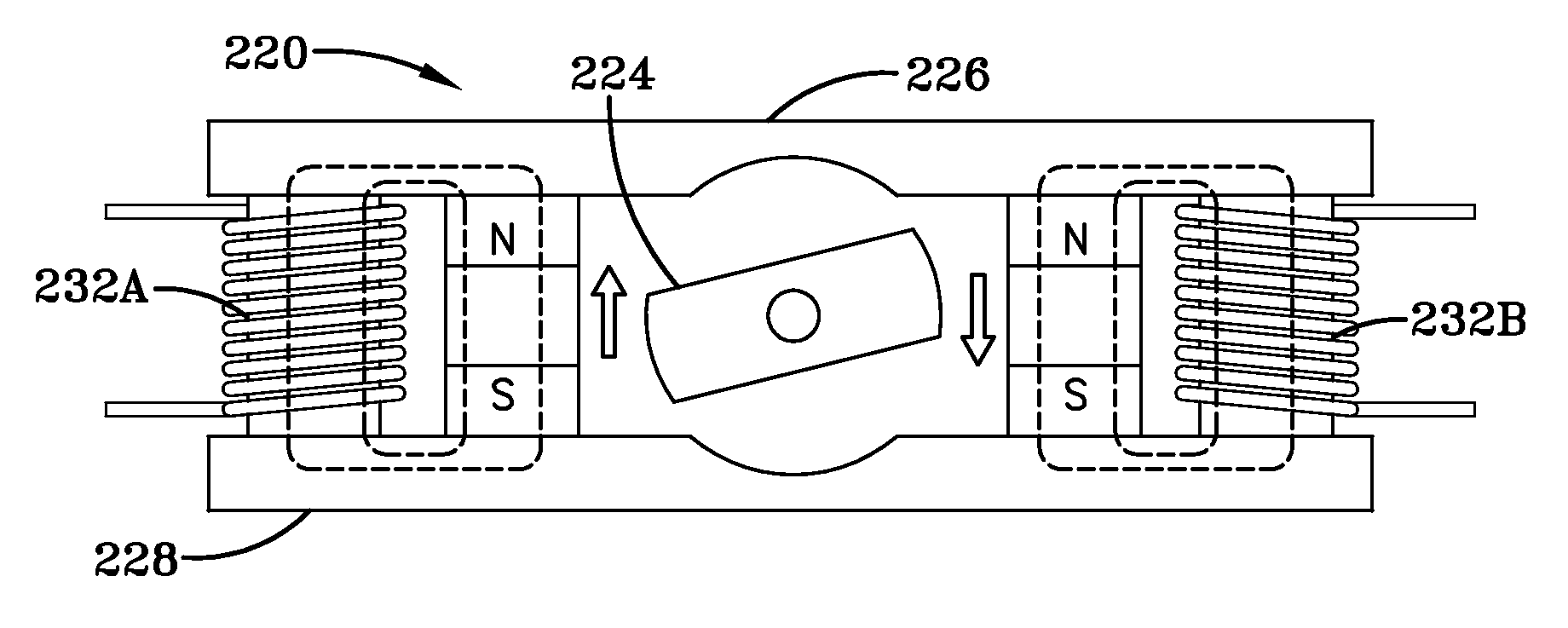
[0076]The inventor made a valve comprising a permanent magnet and an electromagnet such as shown in FIGS. 6 and 7. The permanent magnet was individually capable of creating 70 lbs. of magnetic pull. In the first test, 8 watts of power (i.e., 5 volts DC at 1.6 amps) was supplied to the electromagnet, thereby making the electromagnetic also individually capable of creating 70 lbs. of magnetic pull. In other words, the energy force of the two magnets was substantially equal. When the power was supplied to the electromagnet, the combined magnetic field of the permanent magnet and the electromagnet produced 280 lbs. of lifting force on a load. In a second test, 19.2 watts of power was supplied to the electromagnet. As a result, the magnets were not evenly matched, and the valve was less efficient. Regardless, the valve still produced 350 lbs. of lifting force on a load.

[0077]In a third test, the inventor used two valves situated adjacent to each other. The power supplied to each valve wa...


PUM


Abstract

The present invention is a system and method for utilizing magnetic energy. The basic principles of the present invention may be implemented in a variety of systems and methods. A magnet may be rotated or an electromagnet may be controlled in order to control a magnetic field generated by a set of magnets. As a result, numerous, substantial benefits may be achieved by providing at least one set of multiple magnets. For example, the present invention may be used in systems and methods to perform a variety of functions including, but not limited to: (1) to control, manipulate, hold, and / or release a load; (2) to open and / or close a pathway; (3) to open and / or close a circuit; (4) to apply a magnetic field to a load and / or to remove a magnetic field from a load; (5) to intermittently apply and remove a magnetic field; (6) to increase the magnetic field that may be applied to a load; (7) to induce a load into motion; (8) to create energy; and (9) to improve the energy efficiency of a device or system.

Description

[0001]This is a continuation-in-part of U.S. application Ser. No. 11 / 015,058, filed Dec. 17, 2004 now abandoned. This is also a continuation-in-part of U.S. application Ser. No. 11 / 015,560, filed Dec. 17, 2004. The entirety of each of the above priority documents is incorporated herein by reference.BACKGROUND AND SUMMARY OF THE INVENTION[0002]The present invention relates generally to systems and methods for utilizing magnetic energy. Utilizing the principles of the present invention, various systems and methods for utilizing magnetic energy may be developed. Examples of the present invention include a valve (e.g., a holding or lifting device), a motor, a generator, and other similar or suitable systems and methods.[0003]In general, a magnet is an object that produces a flux field as a result of the effects of molecular alignment or because of the effects of electric current. A traditional use of magnets is for holding metallic objects. In a traditional use of a magnet, a sufficient...

Claims


Application Information

Patent Timeline
IPC IPC(8): H01F7/08
CPCH02K26/00H01F7/0257H01F7/04
Inventor HILDENBRAND, JACK W.
Owner HILDENBRAND JACK W
Learn More