
Radio signal communication method, base station and terminal station

a radio signal and communication method technology, applied in the direction of wireless commuication services, electromagnetic wave modulation, power management, etc., can solve the problem that the fixed multiplexing scheme would unavoidably reduce the sinr and transmission rate of each mobile terminal, and achieve the effect of improving the data transmission ra

Inactive Publication Date: 2008-11-18
HITACHI LTD +1
View PDF10 Cites 38 Cited by
  • Summary
  • Abstract
  • Description
  • Claims
  • Application Information

AI Technical Summary

Benefits of technology

[0011]As described above with reference to the prior art, each multiplexing scheme has both advantages and disadvantages. In order to make the most of the advantages of each multiplexing scheme, it is effective to switch the multiplexing scheme adaptively. Then, the SINR and the transmission rate are prevented from being reduced.
[0012]The propagation environment undergoes a constant change, and therefore a fixed multiplexing scheme would unavoidably reduce the SINR and transmission rate of each mobile terminal. This reduction can be avoided by adaptively switching the multiplexing scheme.
[0015]The use of a signal transmission method in which the multiplexing scheme of the data signal and the pilot signal is adaptively assigned can prevent the SINR reduction at the mobile terminal to which the signal is transmitted, thereby improving the data transmission rate.

Problems solved by technology

The propagation environment undergoes a constant change, and therefore a fixed multiplexing scheme would unavoidably reduce the SINR and transmission rate of each mobile terminal.

Method used


Image

  • Radio signal communication method, base station and terminal station
  • Radio signal communication method, base station and terminal station
  • Radio signal communication method, base station and terminal station

Examples


Embodiment Construction

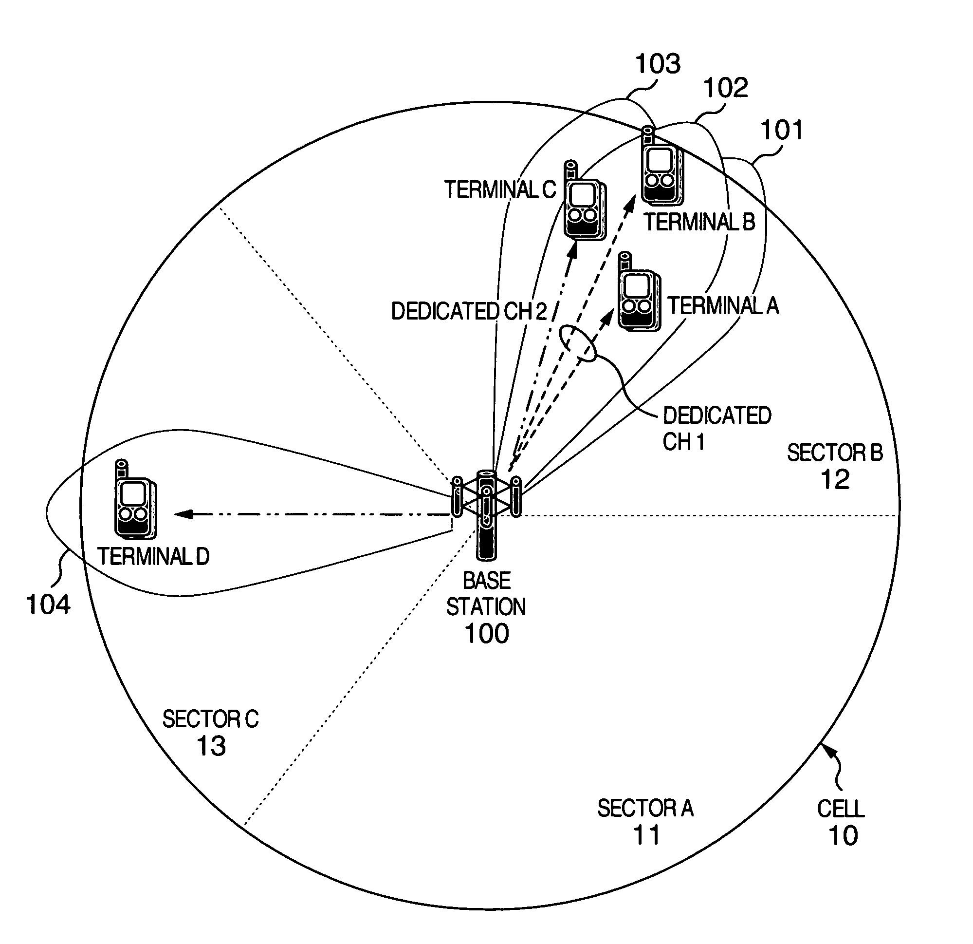
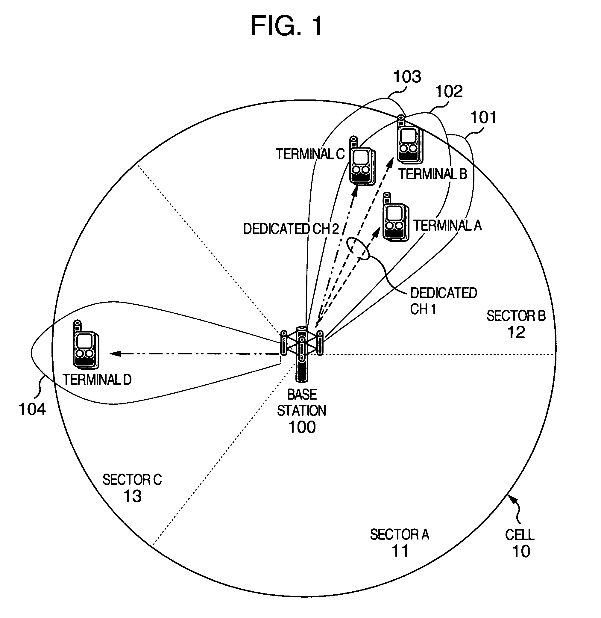
[0034]FIG. 1 shows a network configuration of an example of a communication system between a base station and mobile terminals.

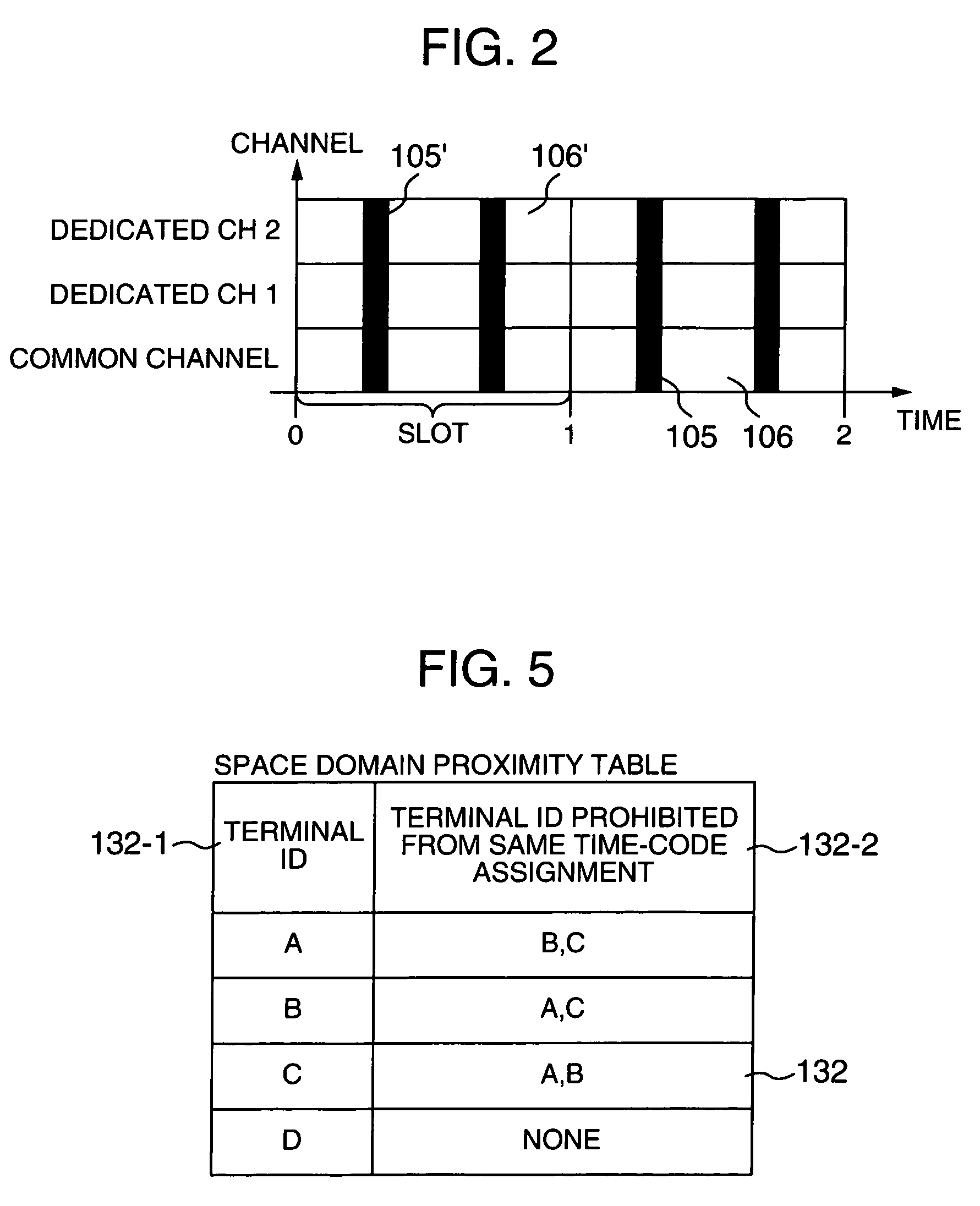
[0035]A base station 100 transmits downlink signals to mobile terminals A, B, C and D using different frequency resources for the different mobile terminals. The base station, in establishing the connection with a mobile terminal, first assigns the mobile terminal to a dedicated channel managed by the base station. The dedicated channels in the number required for simultaneous transmission from the base station are prepared. Each dedicated channel is integrated by the Walsh code assigned to the dedicated channel for code division multiplexing. The base station transmits a downlink packet by selecting a given mobile terminal for each slot of each dedicated channel. By way of explanation, consider a system having two dedicated channels. According to this embodiment, an equal number of mobile terminals are assumed to be assigned to each dedicated channel, and t...


PUM


Abstract

A signal transmission and reception method, and a base station and a mobile terminal therefor are disclosed. In a communication system including a base station and at least a mobile terminal, the transmission of the data signal from the base station to each mobile terminal is controlled in accordance with the manner in which the pilot signal transmitted from the base station to each mobile terminal is received by the mobile terminal. In the signal transmission method, the proper one of a plurality of signal multiplexing schemes is selected based on the control signal received from each mobile terminal, and the transmission signal is multiplexed by the selected signal multiplexing scheme and transmitted to each mobile terminal. The transmission signal includes the data signal and the dedicated pilot signal transmitted to the mobile terminal.

Description

INCORPORATION BY REFERENCE[0001]The present application claims priorities from Japanese applications JP2003-141288 filed on May 20, 2003, and JP2004-116333 filed on Apr. 12, 2004, the contents of which are hereby incorporated by reference into this application.BACKGROUND OF THE INVENTION[0002]The present invention relates to a pilot signal transmission and reception method and a base station and a mobile terminal of a data communication system with a variable data rate in which the packet data transmission rate is increased and the transmission delay is reduced.[0003]WO99 / 23844 discloses a method and an apparatus for increasing the packet data transmission rate and reducing the transmission delay in a data communication system with a variable data rate.[0004]Consider the pilot signal in the prior art. The pilot signal is used for various purposes. The first purpose is to detect a base station which controls a mobile terminal. The second purpose is for a mobile terminal to receive a ...

Claims


Application Information

Patent Timeline
IPC IPC(8): H04B7/216H04B7/04H04B7/08H04B7/26H04J3/00H04J13/00H04J99/00H04W16/28H04W24/02H04W48/08H04W52/04H04W72/02H04W72/04H04W76/02
CPCH04B7/0408H04L5/0003H04L5/0042H04L5/0044H04L5/0051H04L5/006H04L5/0062H04B7/086H04W48/08
Inventor FUJISHIMA, KENZABUROKUWAHARA, MIKIO
Owner HITACHI LTD
Learn More