Fuel consumption evaluation system

a fuel consumption and evaluation system technology, applied in the direction of liquid/fluent solid measurement, relative volume flow measurement, instruments, etc., can solve the problems of deteriorating fuel efficiency, affecting fuel consumption, and evaluation does not always reflect the real cause of fuel efficiency deterioration or improvement, so as to improve the accuracy of fuel consumption

Active Publication Date: 2008-11-25
VOLVO LASTVAGNAR AB
View PDF13 Cites 60 Cited by
  • Summary
  • Abstract
  • Description
  • Claims
  • Application Information

AI Technical Summary

Benefits of technology

[0041]The fuel consumption evaluation system with the configuration and evaluation method according to claims 1 to 11 of the invention divides stored travel data from start to stop into a plurality of phases (E1: start acceleration phase, E2: steady running phase, E3: deceleration phase, E4: idling phase) (FIG. 2),
[0042]sets fuel consumption-related parameters (“start acceleration shift-up engine speed N1 and accelerator opening degree α1” P1, “steady running engine speed N2” P2, “deceleration coasting ratio” P3 and “idling velocity V4” P4 or “(vehicle velocity)2 / distance traveled S” P5) for each of the plural phases (FIG. 4),
[0043]determines fuel consumption (Q1-Q4) for each of the plural phases (E1-E4) based on correlation (correlation line F in FIG. 5) between the parameters and fuel consumption (fuel consumption per unit distance traveled q), and
[0044]makes an evaluation based on the determined fuel consumption (Q).
[0045]The abovementioned parameters (P1-P5) are easily associated with the way of driving to improve the accuracy of fuel consumption (Q) calculated on the basis of these parameters.
[0046]A frequency distribution of travel data in connection with each of the parameters (P1-P5) is nearly a normal distribution (FIG. 4). By processing numerous such travel data, the average (mean value) and the degree of dispersion can be known in the frequency distribution for each of the parameters (P1-P5).

Problems solved by technology

This means that when such predetermined thresholds are not exceeded, the way of driving is not decided to have deteriorated fuel efficiency.
Also, in connection with (3) vehicle velocity, this evaluation method has another problem that since an evaluation is made simply on the basis of vehicle velocity without considering the distance traveled from start to stop, the result of evaluation does not always reflect the real cause of fuel efficiency deterioration or improvement.
However, in actual situations, roads have slopes and the traffic flow varies from time to time, which affects fuel consumption.
Therefore, even when the way of driving is constant, fuel consumption per unit distance may easily deviate from the previously estimated level.
Furthermore, although fuel consumption depends on vehicle total mass including freight or passengers, the influence of slopes and vehicle total mass are not reflected in evaluations.
In addition, the primary object of the above techniques is to encourage the driver to do fuel-efficient driving, but they do not define any means to encourage, in real time, the driver to do fuel-efficient driving.
However, this driving information provision system does not suggest any means for urging fuel-efficient driving in real time.

Method used


Image

  • Fuel consumption evaluation system
  • Fuel consumption evaluation system
  • Fuel consumption evaluation system

Examples


first embodiment

[0128]First, the invention will be described in reference to FIGS. 1 to 7.

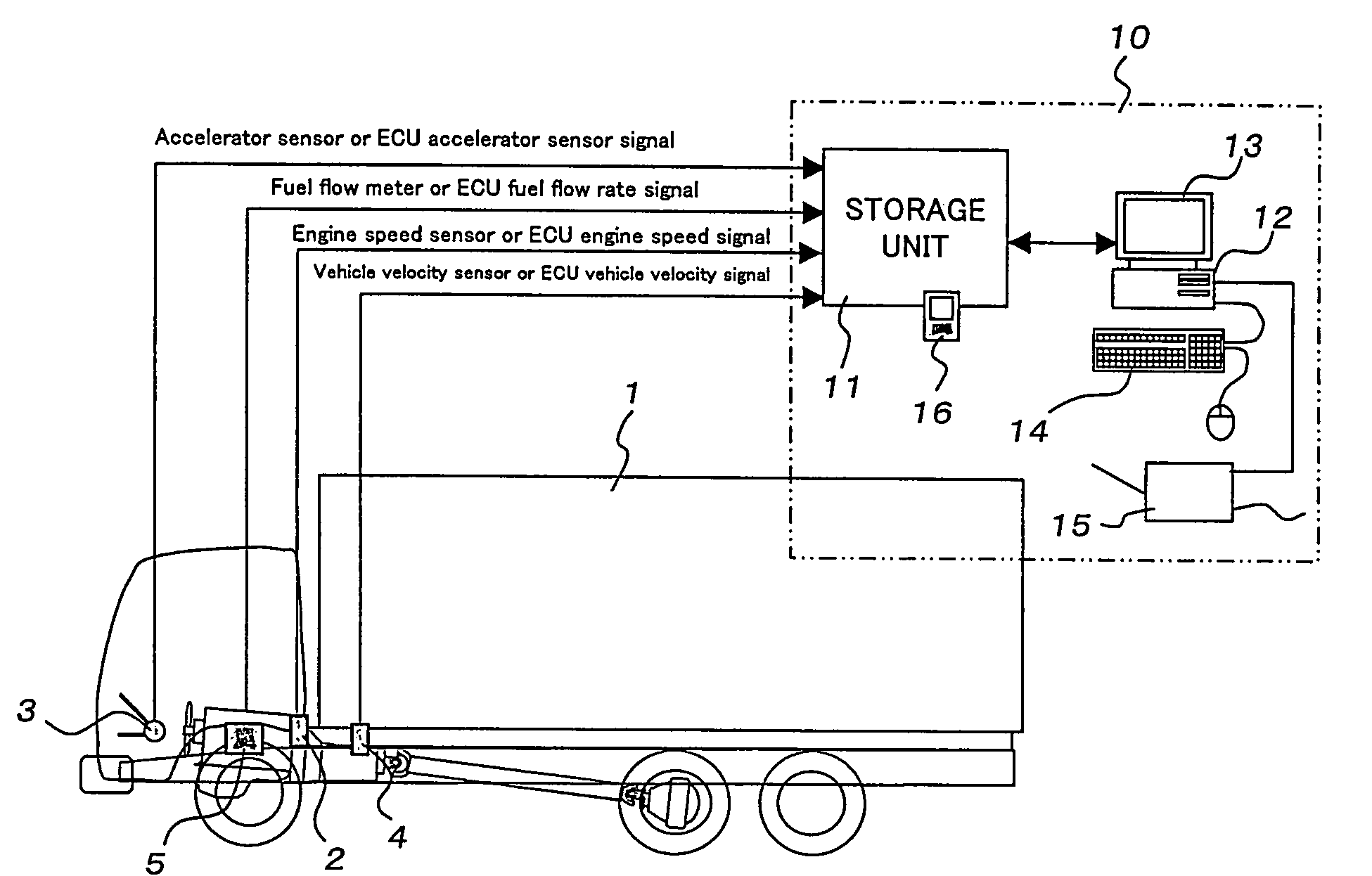
[0129]The fuel consumption evaluation system according to the first embodiment comprises: engine speed measuring means 2 which measures the engine speed (number of revolutions) N of a truck 1 (hereinafter the engine speed measuring means is called the engine speed sensor); accelerator opening degree measuring means 3 which measures accelerator opening degree α (hereinafter the accelerator opening degree measuring means is called the accelerator opening degree sensor); vehicle velocity measuring means 4 which measures vehicle velocity V (hereinafter the vehicle velocity measuring means is called the vehicle velocity sensor); fuel flow rate measuring means 5 which measures fuel flow rate Fw (hereinafter the means is called the fuel meter); and control means 10 which evaluates fuel consumption Q of the truck 1 from the measured engine speed N, accelerator opening degree α, vehicle velocity V, and fuel flow rate F...

second embodiment

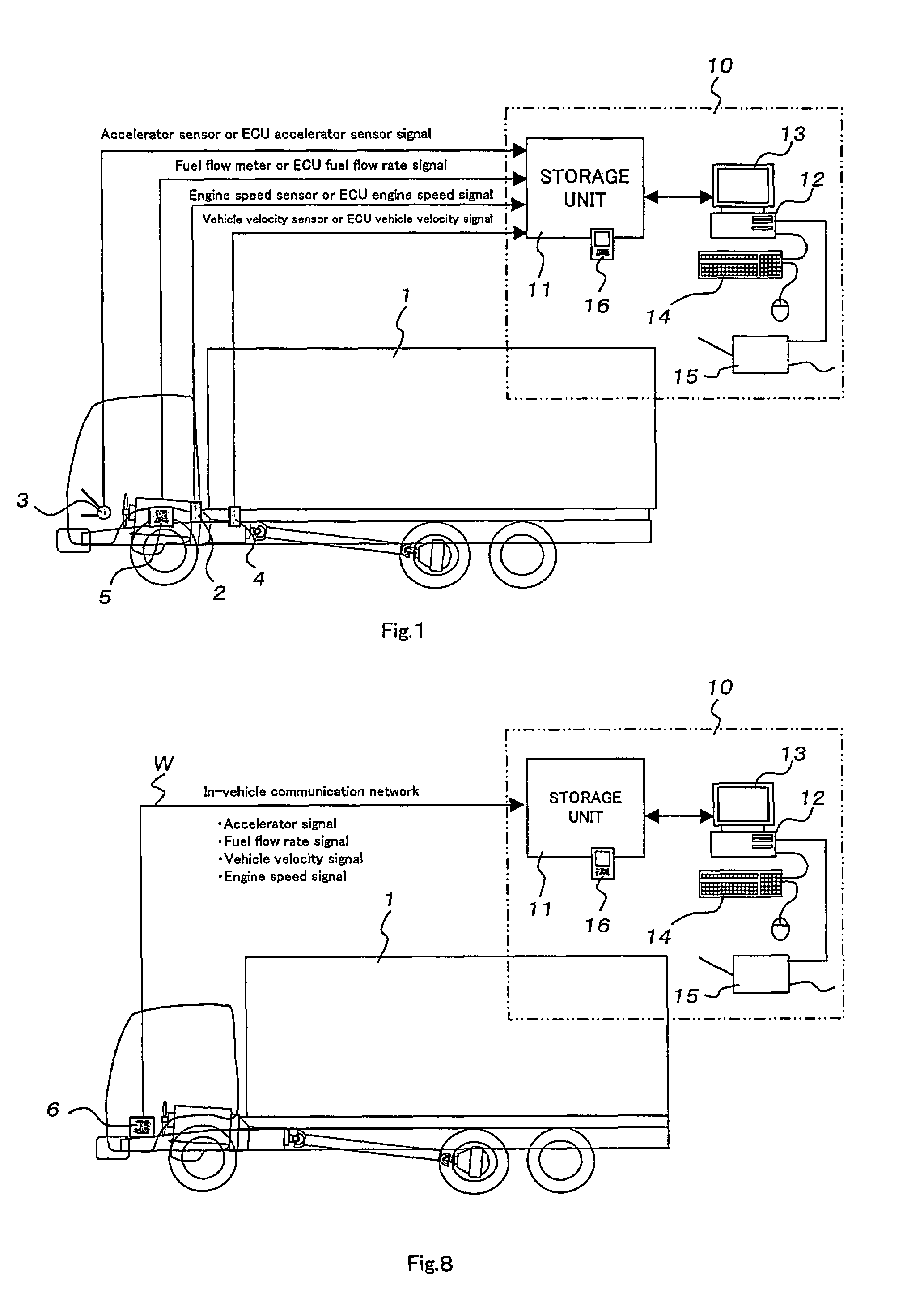
[0189]Next, the invention will be described referring to FIG. 8.

[0190]In the first embodiment as shown in FIGS. 1 to 7, the detection means for various parameters, namely the engine speed sensor 2, accelerator opening degree sensor 3, vehicle velocity sensor 4 and fuel flow meter 5, are connected with the onboard database 11 through exclusive lines respectively.

[0191]On the other hand, in the second embodiment as shown in FIG. 8, an accelerator signal, a fuel flow rate signal, a vehicle velocity signal, and an engine speed signal are collected as digital signals in a LAN repeater 6 by an in-vehicle communication network “in-vehicle LAN” and stored in an onboard database 11 through two wires (communication cable) W. Except these points, the system is substantially equivalent to the first embodiment shown in FIGS. 1 to 7 in all aspects including operation and effects and detailed description of the system is omitted.

third embodiment

[0192]Next, the present invention will be described referring to FIGS. 9 to 18.

[0193]As illustrated in FIG. 9, the fuel consumption evaluation system according to the third embodiment consists of equipment U1 in the vehicle and equipment U2 on the management side and a memory card 15 as a means to transfer data collected by the vehicle equipment U1 to the management side equipment U2.

[0194]The management side here refers to the vehicle management department of the freight company which owns the vehicle or the like.

[0195]The vehicle equipment U1 comprises: engine speed measuring means 2 which measures the engine speed (number of revolutions) of the vehicle (truck in the figure) 1 (hereinafter the engine speed measuring means is called the engine speed sensor); accelerator opening degree measuring means 3 which measures accelerator opening degree α (hereinafter the accelerator opening degree measuring means is called the accelerator opening degree sensor); vehicle velocity measuring m...


PUM

PropertyMeasurementUnit
speedaaaaaaaaaa
vehicle velocityaaaaaaaaaa
velocityaaaaaaaaaa

Abstract

The present invention is intended to provide a fuel consumption evaluation system which obtains quantitative data to determine whether actual driving has consumed fuel more efficiently or less efficiently than average driving and gives the driver and / or manager concrete advice for fuel-efficient driving based on the obtained data, and also provide a fuel consumption evaluation system which decides, based on obtained fuel efficiency data, whether driving is more fuel-efficient than average driving and sets a target and gives the driver and / or manager concrete advice for fuel-efficient driving based on the obtained data in consideration of change in vehicle total mass without any influence of slopes and traffic flows and particularly encourages and instructs, in real time, the driver to do fuel-efficient driving. The system comprises: engine speed measuring means (2) which measures engine speed of a truck (1); accelerator opening degree measuring means (3) which measures an accelerator opening degree (α); vehicle velocity measuring means (4) which measures vehicle velocity (V); fuel flow rate measuring means (5) which measures a fuel flow rate (Fw); and control means (10) which evaluates fuel consumption of the truck from measured engine speed (N), accelerator opening degree (α), vehicle velocity (V) and fuel flow rate (Fw).

Description

TECHNICAL FIELD[0001]The present invention relates to a system which evaluates a vehicle's driving conditions such as fuel consumed per unit distance traveled (hereinafter called “fuel efficiency”) and also to a system which evaluates driving conditions related to fuel consumption for vehicles in which the difference in vehicle total mass between the unloaded condition and loaded condition is large, such as trucks and buses.BACKGROUND ART[0002]A technique which encourages a driver to improve his / her driving skill and improves fuel efficiency by an improved driving skill has been publicized (for example, see Patent Document 1).[0003]The above technique uses five parameters for judgment: (1) acceleration, (2) deceleration, (3) vehicle velocity, (4) driving in which a driver does not shift up though he / she can do so, and (5) engine idling.[0004]In this technique, if predetermined thresholds for the parameters (1) to (3) are exceeded, the way of driving concerned is decided to have dete...

Claims


Application Information

Patent Timeline
Patent Type & Authority Patents(United States)
IPC IPC(8): G01L3/26
CPCG01F9/02B60K2350/1092Y02T10/84B60K2370/174
Inventor NISHIYAMA, YOSHITAKAYAMASHITA, MASARUMIYAKE, HIROSHINAKAMURA, AKIRA
Owner VOLVO LASTVAGNAR AB
Why Eureka
Try Eureka