
Battery charging apparatus for charging a plurality of batteries

Inactive Publication Date: 2008-11-25
SANYO ELECTRIC CO LTD
View PDF8 Cites 26 Cited by
  • Summary
  • Abstract
  • Description
  • Claims
  • Application Information

AI Technical Summary

Benefits of technology

[0005]The present invention was developed to resolve these types of drawbacks. Thus it is a primary object of the present invention to provide a battery charging apparatus for charging a plurality of batteries which can rapidly charge a plurality of rechargeable batteries in a short period while keeping charging circuit output current small, and in addition can charge batteries to full charge under ideal conditions while preventing over-charging of each individual rechargeable battery to effectively prevent battery performance degradation.
[0008]Further, the charging current in each series connected rechargeable battery can be controlled in the battery charging apparatus described above. This is because the duty factor of each charging unit can be changed by switching the series switch and parallel switch ON and OFF, and the charging mode of each charging unit can be switched between charging and cut-off at a prescribed duty factor. Therefore, over-charging of a charge capacity depleted rechargeable battery and battery performance degradation can be reliably prevented. Consequently, the battery charging apparatus described above has the characteristic that batteries can be charged under ideal conditions while preventing over-charging of each rechargeable battery, and effectively preventing battery performance degradation.

Problems solved by technology

However, the charging current of each individual rechargeable battery cannot be controlled when the batteries are connected in series for charging.
Consequently, when repeatedly recharged, the rechargeable battery with the most depleted battery capacity will be over-charged and its performance will degrade.
Since the charge capacity of the degraded battery will suffer further reduction, that battery will be further over-charged and degrade abruptly.

Method used


Image

  • Battery charging apparatus for charging a plurality of batteries
  • Battery charging apparatus for charging a plurality of batteries
  • Battery charging apparatus for charging a plurality of batteries

Examples


Embodiment Construction

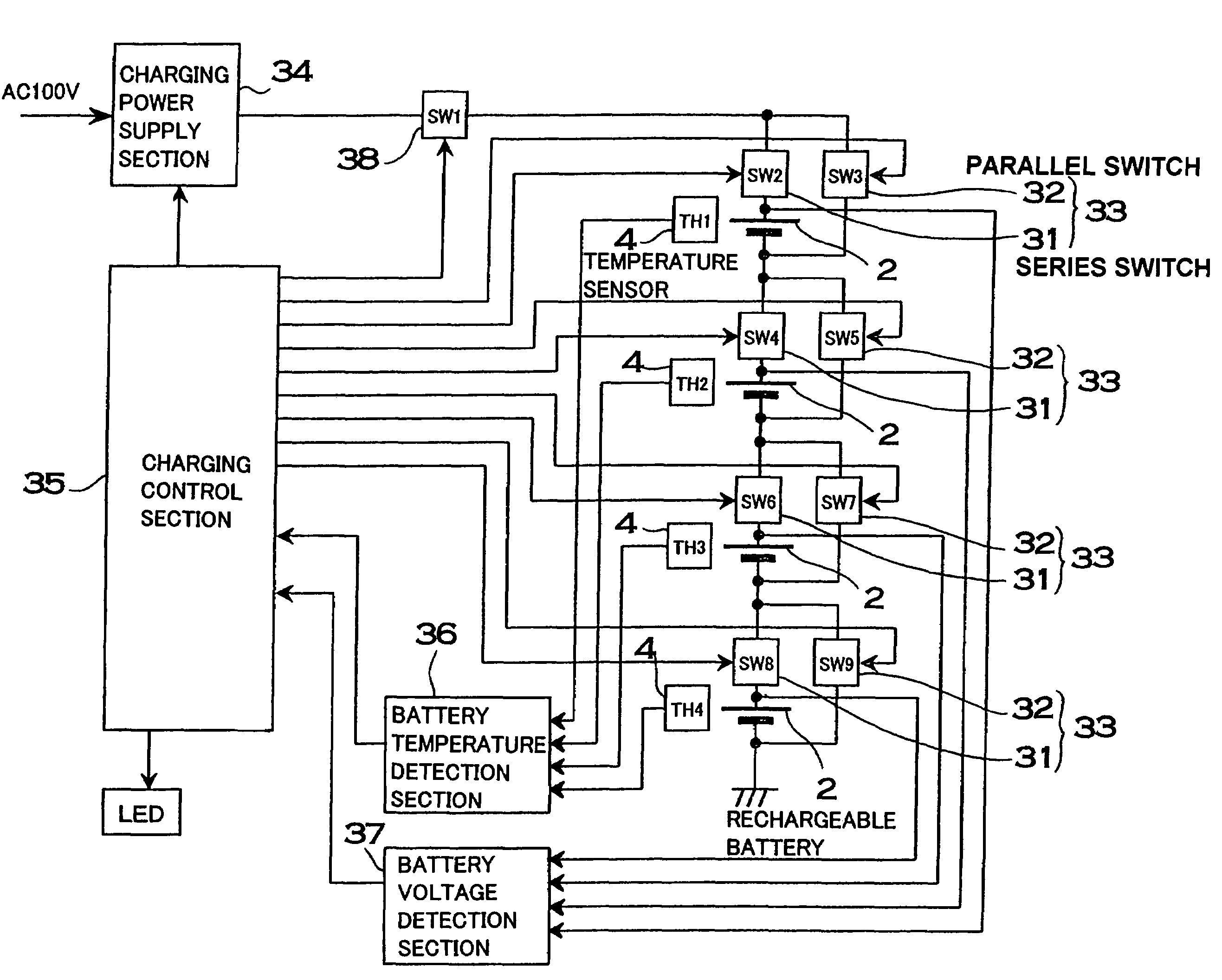
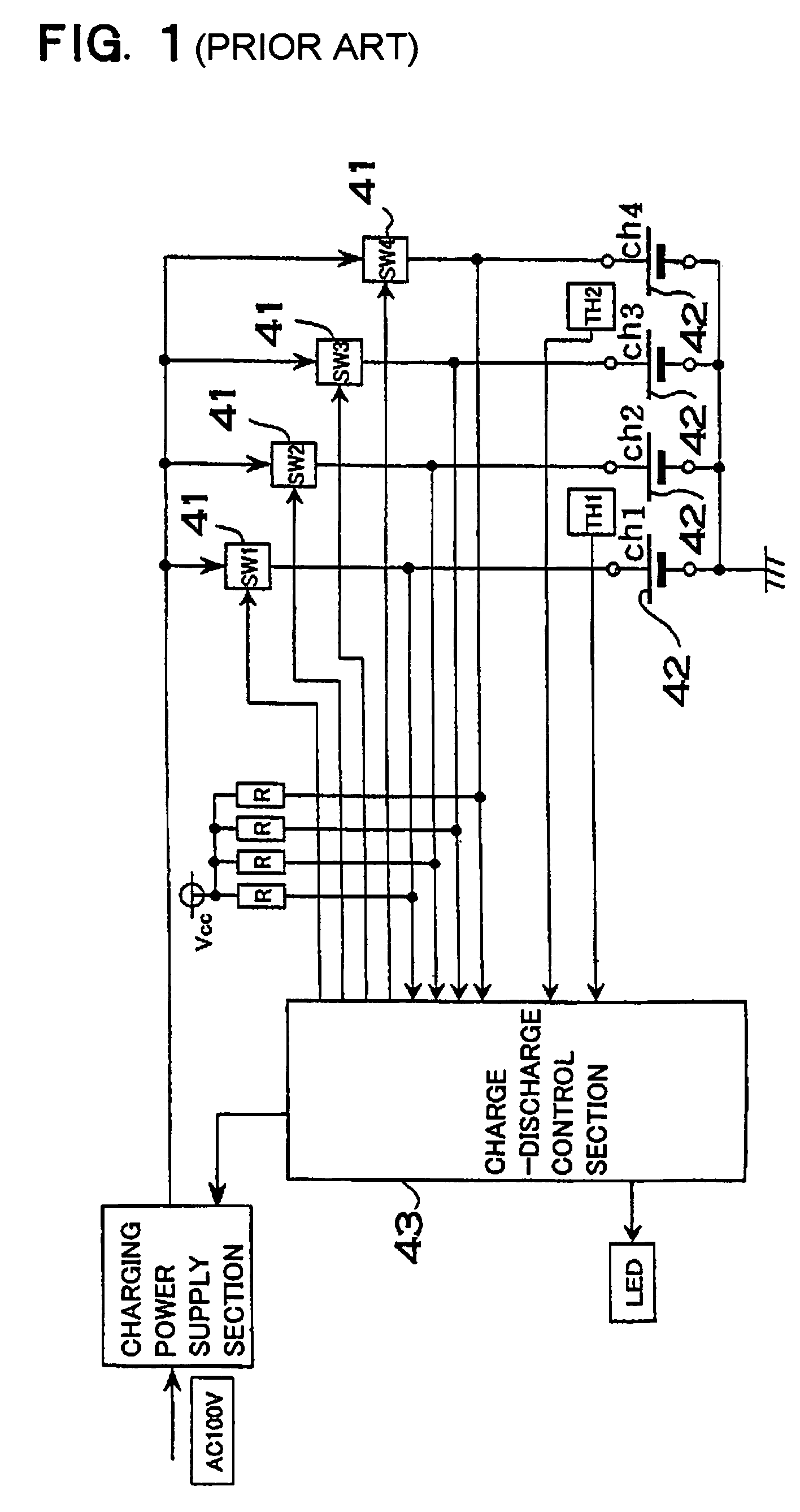
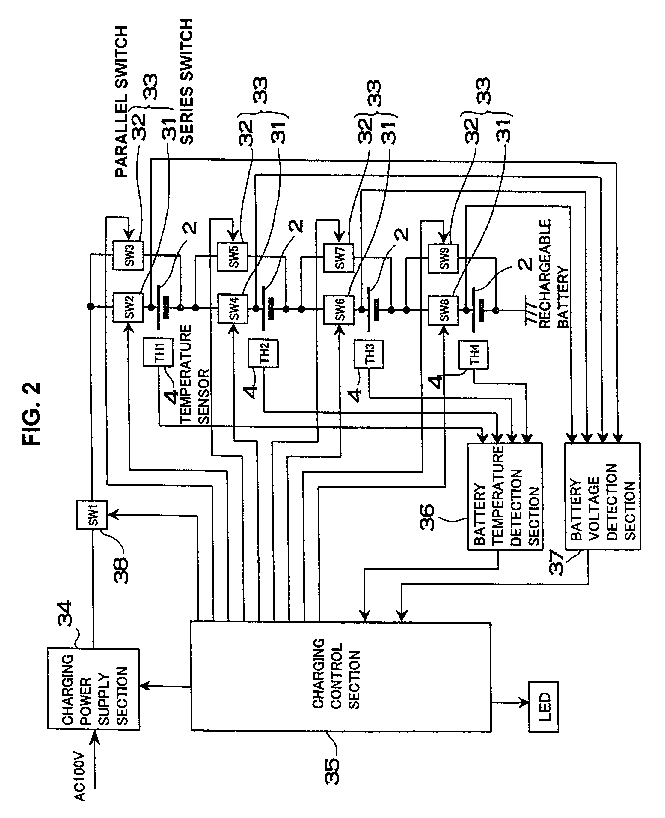
[0029]The battery charging apparatus shown in FIG. 2 is provided with a plurality of series connected charging units 33, a charging power supply section 34 which passes current through the series connected charging units 33, and a charging control section 35 which switches series switches 31 and parallel switches 32 of the charging units 33 ON and OFF to control rechargeable battery charging.

[0030]Each charging unit 33 is provided with a series switch 31 connected in series with a rechargeable battery 2, and a parallel switch 32 connected in parallel with the series connected rechargeable battery 2 and series switch 31. The series switch 31 is turned ON when the rechargeable battery 2 is being charged, and OFF when the battery is not being charged. The parallel switch 32 is turned OFF when the rechargeable battery 2 is being charged, and ON when bypassing the charging current. When a parallel switch 32 is ON, current flowing through the charging unit 33 does not flow through the rec...


PUM


Abstract

A battery charging apparatus having a plurality of charging units connected in series. A charging unit has a series switch connected in series with a rechargeable battery, and a parallel switch connected in parallel with the series connected rechargeable battery and series switch. A charging control section controls charging of a rechargeable battery by switching the series switch and parallel switch ON and OFF. The charging control section changes the duty factor for switching series switches and parallel switches ON and OFF, switches a charging unit between a charging mode and a cut-off mode at a prescribed duty factor, and controls rechargeable battery charging currents to charge a plurality of batteries.

Description

BACKGROUND OF THE INVENTION[0001]This invention relates to a battery charging apparatus which charges a plurality of rechargeable batteries connected in series.[0002]A battery charger, which charges a plurality of rechargeable batteries, connects those batteries in parallel for charging [refer to Japanese Patent Application 2002-298930]. As shown in FIG. 1, the battery charger cited in this disclosure connects switches 41 in series with each rechargeable battery 42, and those switches 41 are turned ON and OFF by a charging control section 43. A rechargeable battery 42 is charged when a switch is turned ON and charging is suspended when the switch is turned OFF. The charging control section 43 keeps a switch 410N until the rechargeable battery 42 has reached full charge, and turns the switch 41 OFF when the rechargeable battery 42 is fully charged. Since all the rechargeable batteries 42 do not become fully charged at the same time, the switches 41 are turned OFF as the connected rec...

Claims


Application Information

Patent Timeline
IPC IPC(8): H02J7/00H02J7/06H02J7/02H01M10/44H02J7/04
CPCH02J7/0016H02J7/041H02J7/045H02J7/047H02J2007/0037H02J7/00302H02J7/0071H02J7/007194H02J7/04H02J7/007182H02J7/007192
Inventor YAMASHITA, TAKAHIRO
Owner SANYO ELECTRIC CO LTD
Features
  • Generate Ideas
  • Intellectual Property
  • Life Sciences
  • Materials
  • Tech Scout
  • Unparalleled Data Quality
  • Higher Quality Content
  • 60% Fewer Hallucinations
Learn More