Air quantity estimation apparatus for internal combustion engine

a technology for internal combustion engines and air quantity estimation, which is applied in the direction of electrical control, process and machine control, instruments, etc., can solve the problems of time delay in relation, inability to accurately estimate cylinder-interior air quantity, etc., to achieve accurate estimation

Inactive Publication Date: 2008-11-25
TOYOTA JIDOSHA KK
View PDF37 Cites 20 Cited by
  • Summary
  • Abstract
  • Description
  • Claims
  • Application Information

AI Technical Summary

Benefits of technology

[0015]By virtue of this configuration, a detection delay of the air flowmeter in relation to the compressor-inflow-air flow rate which is a flow rate of air actually flowing into the compressor is compensated for. Therefore the compressor-inflow-air flow rate at the present time point can be accurately estimated. Further, the estimated compressor-inflow-air flow rate at the present time point as the compressor-outflow-air flow rate which is a flow rate of air flowing out of the compressor at the present time point, is applied to the air model, whereby the cylinder-interior air quantity is estimated. As a result, the cylinder-interior air quantity can estimated accurately.
[0059]Moreover, the latest actual opening of the throttle valve of all the actual openings of the throttle valve having been calculated before the present time point and the obtained compressor-inflow-air flow rate at the present time point are applied to the air model. By virtue of this configuration, the opening of the throttle valve and the compressor-inflow-air flow rate based on the electrical physical quantities output at mutually close time points, respectively, can be applied to the air model. As a result, the cylinder-interior air quantity can be accurately estimated.

Problems solved by technology

Accordingly, the cylinder-interior air quantity cannot be accurately estimated unless the pressure and temperature of throttle-valve upstream air are accurately estimated.
Therefore, possibly, the cylinder-interior air quantity cannot be accurately estimated when a pressure and a temperature detected by an intake-air pressure sensor and an intake-air temperature sensor are employed as the pressure and temperature of the throttle-valve upstream air.
However, the flow rate of air detected by the hot-wire air flowmeter involves a time delay in relation to the actual flow rate of air, the time delay stemming from time required for transfer of heat between air and the hot wire and time required to heat the hot wire.
Such detection delay occurs not only when a hot-wire air flowmeter is used but also when the other type of air flowmeter is used.
Accordingly, when the compressor-inflow-air flow rate varies within a short period of time; for example, a transition period during which the operation conditions (load, engine speed, etc.) vary, there arises a problem that the pressure and temperature of throttle-valve upstream air cannot be accurately estimated even when the detected compressor-inflow-air flow rate is employed as the compressor-outflow-air flow rate, because the compressor-inflow-air flow rate detected by means of the air flowmeter greatly differs from the actual compressor-inflow-air flow rate.

Method used


Image

  • Air quantity estimation apparatus for internal combustion engine
  • Air quantity estimation apparatus for internal combustion engine
  • Air quantity estimation apparatus for internal combustion engine

Examples


Embodiment Construction

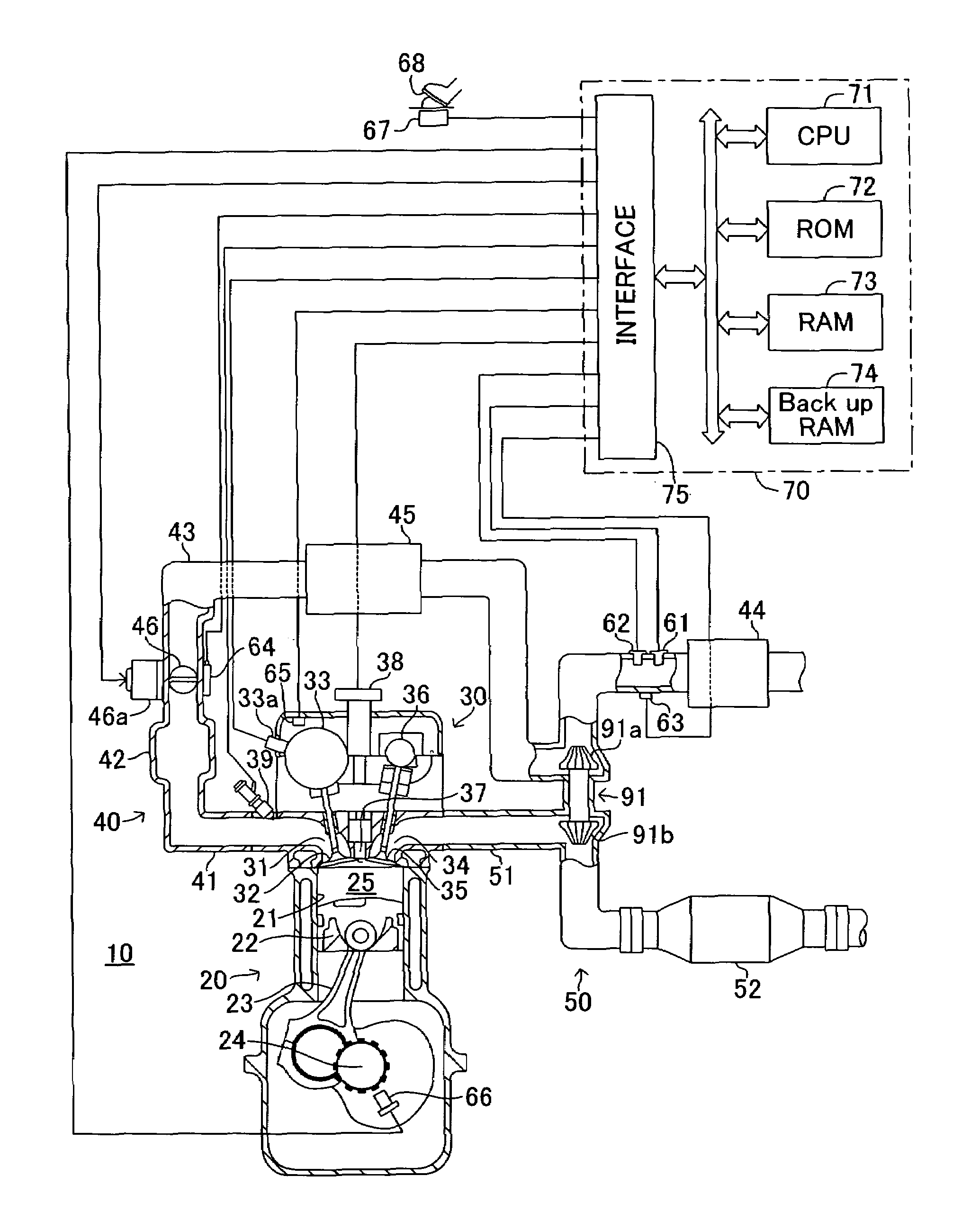
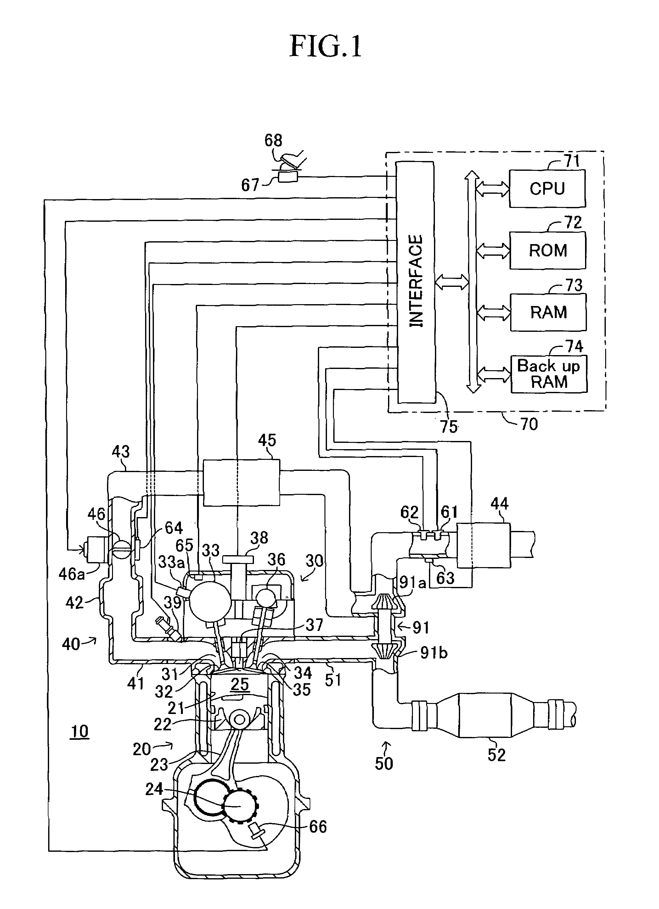
[0081]An embodiment of an air quantity estimation apparatus for an internal combustion engine according to the present invention will be described with reference to the drawings. FIG. 1 shows a schematic configuration of a system configured such that the air quantity estimation apparatus is applied to a spark-ignition multi-cylinder (e.g., 4-cylinder) internal combustion engine. FIG. 1 shows only a cross section of a specific cylinder; however, the remaining cylinders have the similar configuration.

[0082]The internal combustion engine 10 includes a cylinder block section 20 including a cylinder block, a cylinder block lower-case and an oil pan; a cylinder head section 30 fixed on the cylinder block section 20; an intake system 40 for supplying gas mixture of fuel and air to the cylinder block section 20; and an exhaust system 50 for emitting exhaust gas from the cylinder block section 20 to the exterior of the engine.

[0083]The cylinder block section 20 includes cylinders 21, pistons...


PUM


Abstract

This air quantity estimation apparatus inputs an output quantity Vafm of an air flowmeter 61 disposed in an intake passage upstream of a compressor 91a to an AFM inverse model M1 to thereby estimate the flow rate (compressor-inflow-air flow rate) mcmi of air actually flowing into the compressor, which flow rate has been compensated for detection delay. This apparatus estimates the quantity of air introduced in a cylinder (cylinder-interior air quantity) Klfwd at a future time point after the present time point on the basis of the estimated actual compressor-inflow-air flow rate mcmi employed as a flow rate of air actually flowing out of the compressor at the present time point, and first and second air models M10 and M20 which describe the behavior of air within the intake passage downstream of the compressor in accordance with physical laws.

Description

TECHNICAL FIELD[0001]The present invention relates to an apparatus for estimating the quantity of air having been introduced into a cylinder of an internal combustion engine.BACKGROUND ART[0002]Conventionally, there have been known apparatus for estimating a cylinder-interior air quantity (quantity of air having been introduced into a cylinder of an internal combustion engine) by making use of a physical model modeling the behavior of air flowing through the intake passage of the internal combustion engine.[0003]Japanese Patent Application Laid-Open (kokai) No. 2003-184613 discloses one of such apparatus. The disclosed apparatus uses the physical model in which the cylinder-interior air quantity to be estimated is represented by equations including terms regarding a pressure and a temperature of air upstream of a throttle valve (throttle-valve upstream air) and regarding the pressure and temperature of air downstream of the throttle valve (throttle-valve downstream air). Accordingly...

Claims


Application Information

Patent Timeline
Patent Type & Authority Patents(United States)
IPC IPC(8): F02D41/14G01M15/00G06F19/00F02B37/00F02B39/16F02D45/00
CPCF02B39/16F02D41/18F02B29/0425F02B29/0437F02B37/00F02D13/0223F02D23/00F02D41/0007F02D2041/1434F02D2200/0402F02D2041/141F02D45/00
Inventor TANAKA, SATORU
Owner TOYOTA JIDOSHA KK
Why Eureka
Try Eureka