Temperature sensor that achieves a fast response in an exhaust gas environment

a temperature sensor and exhaust gas technology, applied in the field of temperature sensors, can solve the problems that devices, however, have not been found to work in such a scenario, and achieve the effects of improving the response time and accuracy of the temperature sensor, and fast response tim

Inactive Publication Date: 2008-12-02
HONEYWELL INT INC
View PDF11 Cites 26 Cited by
  • Summary
  • Abstract
  • Description
  • Claims
  • Application Information

AI Technical Summary

Benefits of technology

[0017]It is a further aspect of the present invention to provide for a system and method for achieving a fast response time in an RTD-based closed temperature sensor utilized in automotive exhaust gas environments.
[0018]It is also an aspect of the present invention to provide a Closed Sensing Tip housing a temperature sensing element with improved response and accuracy.
[0019]It is yet a further aspect of the present invention to provide a suitable packaging that functions accurately for long term in a harsh, corrosive, high temperature, high pressure, varying gas density environment such as that found in the exhaust gas of automobiles.
[0020]The aforementioned aspects of the invention and other objectives and advantages can now be achieved as described herein. A temperature sensor and method of forming the same is disclosed, which includes a temperature sensing portion having a metal housing configured with at least one circular fin on a surface of the metal housing. A temperature sensing element is generally associated with the temperature sensing portion, wherein a potting is located within a gap formed between the temperature sensing element and the metal housing and joined with a ceramic tube for carrying a plurality of high temperature metal lead wires to and from the temperature sensing portion, thereby forming a temperature sensor utilized in an exhaust gas environment to measure temperature and improve a response time and accuracy of the temperature sensor due to an increase in surface area for convection heat transfer.

Problems solved by technology

Such devices, however, have not been found to work in such a scenario because of the physical limitations of mass-to-area ratio (m / a), which governs the response time.

Method used


Image

  • Temperature sensor that achieves a fast response in an exhaust gas environment
  • Temperature sensor that achieves a fast response in an exhaust gas environment
  • Temperature sensor that achieves a fast response in an exhaust gas environment

Examples


Embodiment Construction

[0027]The particular values and configurations discussed in these non-limiting examples can be varied and are cited merely to illustrate at least one embodiment and are not intended to limit the scope of the invention.

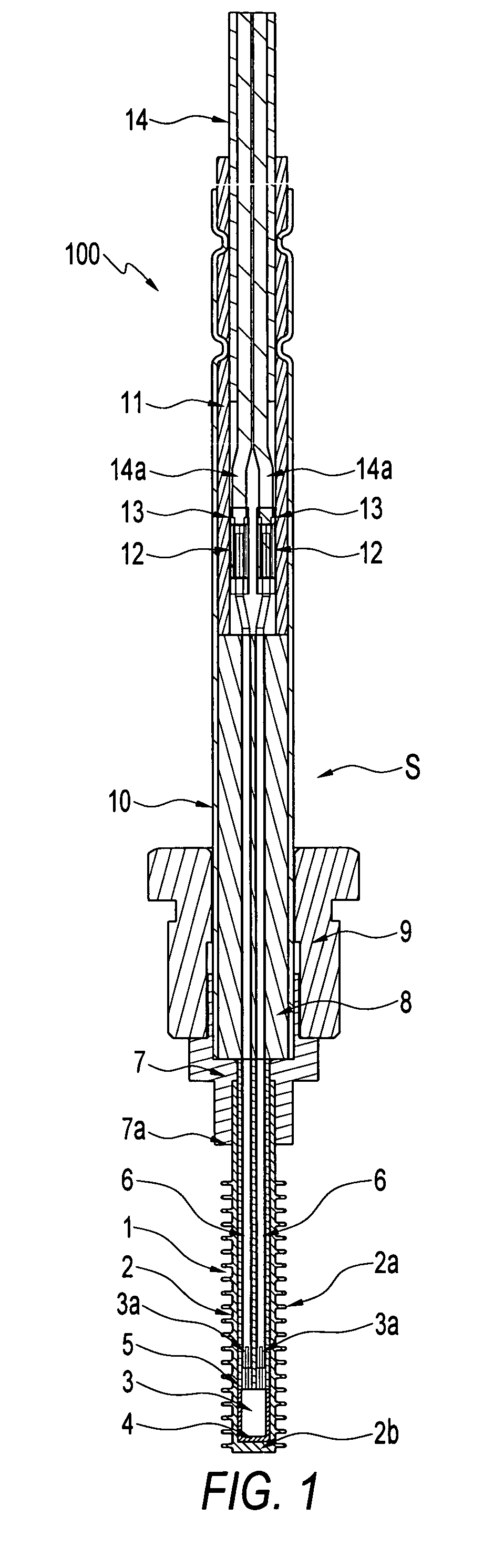
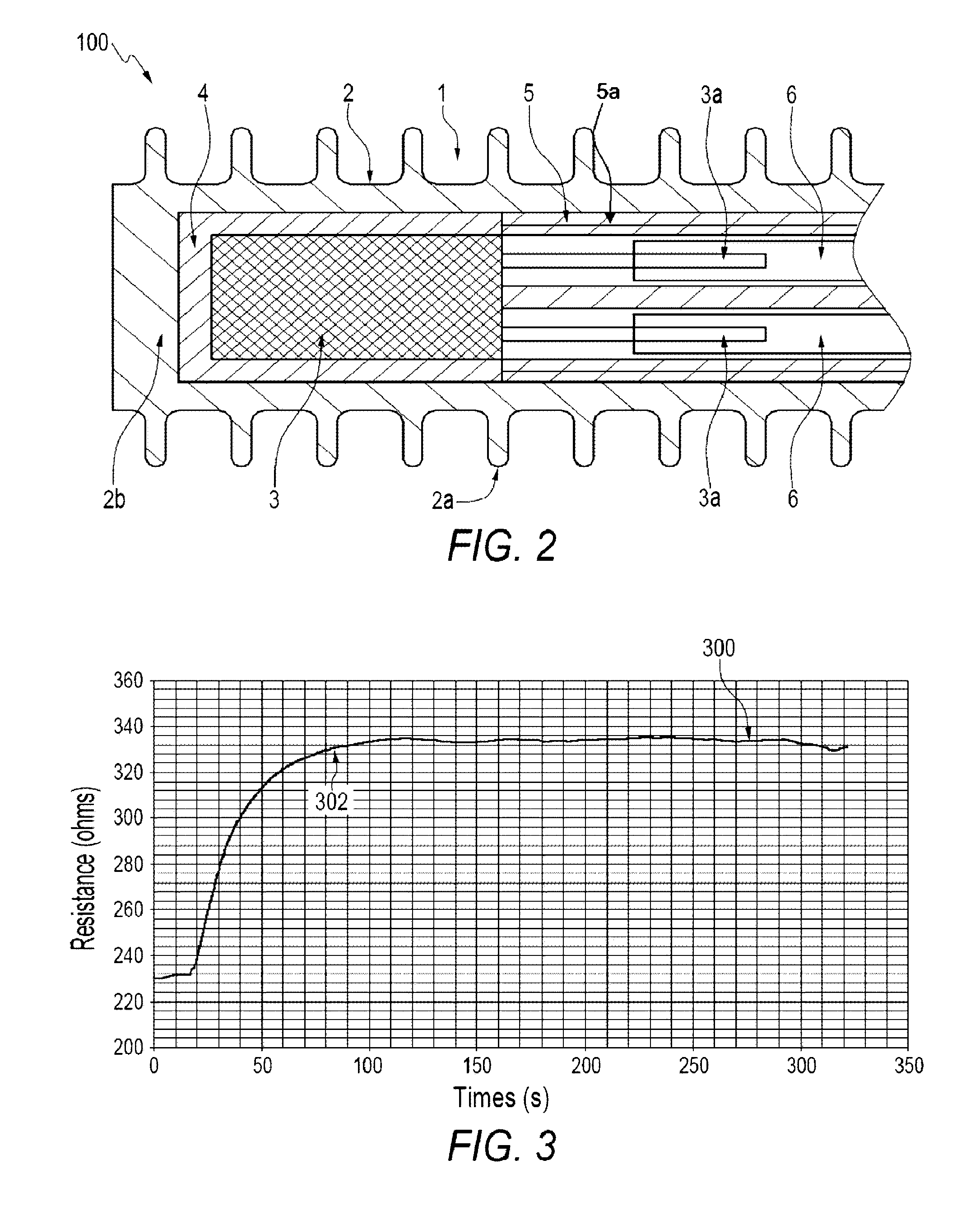
[0028]FIG. 1 illustrates a partial sectional view of a temperature sensor 100, which can be implemented in accordance with a preferred embodiment. FIG. 2 illustrates an enlarged sectional view of the temperatures sensor 100 depicted in FIG. 1 in accordance with a preferred embodiment. Note that in FIGS. 1-2, identical or similar parts or elements are generally indicated by identical reference numerals. FIGS. 1-2 indicate that a temperature sensing portion 1 of the temperatures sensor 100 can be provided with a metal housing 2 having circular fins 2a on its surface composed of a temperature sensing element 3 and a high temperature potting 4 filled in a gap between the temperature sensing element 3 and finned metal housing 2 with a ceramic tube 5 for carrying the high te...


PUM

PropertyMeasurementUnit
dynamic response timeaaaaaaaaaa
temperatureaaaaaaaaaa

Abstract

A temperature sensor and method of forming the same includes a temperature sensing portion having a metal housing configured with at least one circular fin on a surface of the metal housing. A temperature sensing element is generally associated with the temperature sensing portion, wherein a potting is located within a gap formed between the temperature sensing element and the metal housing and joined with a ceramic tube for carrying a plurality of high temperature metal lead wires to and from the temperature sensing portion, thereby forming a temperature sensor utilized in an exhaust gas environment to measure temperature and improve a response time and accuracy of the temperature sensor due to an increase in surface area of the sensor tip for a given thermal mass for convection heat transfer.

Description

TECHNICAL FIELD[0001]Embodiments are generally related to sensor systems and methods. Embodiments are also related to temperature sensors. Embodiments are additionally related to temperature sensors utilized in harsh and corrosive conditions such as, for example, exposure to the exhaust gas of automobiles.BACKGROUND[0002]Temperature sensors are utilized in a variety of applications. For example, temperature sensors that are used in conjunction with ovens typically comprise a metallic tube in which a temperature sensitive element is disposed inside one end with conductive wires extending within the tube from the temperature sensitive element to an opening at the other end of the tube. The metallic tube is inserted through a wall of the oven to permit the temperature sensitive element to be placed in thermal communication with the internal cavity of the oven. The temperature sensitive element is typically a resistive temperature detector, or RTD. The temperature sensor can be also bas...

Claims


Application Information

Patent Timeline
Patent Type & Authority Patents(United States)
IPC IPC(8): G01K1/08G01K13/00G01K7/16
CPCG01K1/16G01K1/18G01K2205/04G01K13/02G01K13/024
Inventor KRISHNAMURTHY, GURUPRASADANILKUMAR, RAMESHBURNETT, ALFRED COLIN
Owner HONEYWELL INT INC
Why Eureka
Try Eureka