Guide vane ring of a turbomachine and associated modification method

a technology of turbomachines and ring rings, which is applied in the direction of machines/engines, stators, liquid fuel engines, etc., can solve the problems of particularly intensive fixing of vanes or vane groups on the vane carrier, and achieve the effect of reducing the risk of crack formation

Inactive Publication Date: 2008-12-02
ANSALDO ENERGIA IP UK LTD
View PDF4 Cites 10 Cited by
  • Summary
  • Abstract
  • Description
  • Claims
  • Application Information

AI Technical Summary

Benefits of technology

[0009]The invention is intended to remedy this. The invention is concerned with the problem of indicating, for a guide vane ring of the type initially mentioned, a possibility which reduces the risk of crack formation on the vanes.
[0010]One aspect of the present invention includes the general idea of designing the fastening of vanes or vane groups on the vane carrier in such a way that these can absorb a dimensional change in the vane carrier, without particularly high stresses occurring in this case in the vane. This is achieved in that, within the tie-up between vane root and vane carrier, degrees of freedom are provided in a controlled way, which permit deformations of the vane carrier typically occurring in the case of thermal loads on the vane carrier, so that such a deformation of the vane carrier leads to no distortion, or only to reduced distortion, in the vane root and therefore in the respective vane or vane group.
[0011]For this purpose, the invention proposes, in the case of one flange, for example the inlet flange, to provide both on a front end portion in the circumferential direction and on a rear end portion in the circumferential direction, both radially on the inside and radially on the outside, in each case a contact zone which bears against the vane carrier. In contrast to this, on the other flange, that is to say, for example, on the outlet flange, on one end portion, for example on the front end portion, radially on the inside, a contact zone is provided which bears against the vane carrier, whereas this end portion is spaced apart from the vane carrier radially on the outside. On the other end portion in each case, that is to say, for example, on the rear end portion, radially on the outside, a contact zone which bears against the vane carrier is then again provided, whereas this end portion is then spaced apart from the vane carrier radially on the inside. Thus, in the case of one of the flanges, that is to say, here, for example, on the outflow-side outlet flange, the contact zones are arranged diametrically opposite with respect to the end portions or the end portions are positioned, diametrically opposite, so as to be spaced apart from the vane carrier. This results, in each end portion of the vane root, in a degree of freedom which permits a change in radius of the vane carrier and a distortion of the vane carrier. At the same time, it is proposed that the flanges, between their end portions, be spaced apart from the vane carrier both radially on the inside and radially on the outside. Thus, the contact zones of the front end portion are at as great a distance as possible from the contact zones of the rear end portion, with the result that a particularly high elasticity is provided in the vane root. Correspondingly, in the region of its flanges, the vane root can also elastically absorb relatively pronounced dimensional changes of the vane carrier, so that critical loads and distortions of the vane root and therefore of the vanes or vane groups can be avoided or reduced.
[0012]According to a particularly advantageous embodiment, the spacings, arranged diametrically with respect to the end portions, between the flange and the vane carrier may be dimensioned such that, when the turbomachine is operating normally, a pressure difference prevailing between the inflow side and outflow side reduces the spacing owing to the elastic flexural deformation of the vane or vane group and / or of the vane carrier and brings the corresponding end portion to bear against the vane carrier. In other words, during normal operation, the respective vane root is supported on the vane carrier at both end portions and at both flanges both radially on the inside and radially on the outside, thus resulting in a particularly intensive fixing of the vane or vane group on the vane carrier. In transient operating states, that is to say in those in which reduced pressure differences prevail between the inflow side and outflow side and the deformations of the vane carrier mainly take place, the desired spacings between vane root and vane carrier at the one flange can then form diametrically with respect to the end portions. Correspondingly, the vane root can then follow more closely the changing geometry of the vane carrier, thus reducing the load on the vanes.

Problems solved by technology

This results, in each end portion of the vane root, in a degree of freedom which permits a change in radius of the vane carrier and a distortion of the vane carrier.
In other words, during normal operation, the respective vane root is supported on the vane carrier at both end portions and at both flanges both radially on the inside and radially on the outside, thus resulting in a particularly intensive fixing of the vane or vane group on the vane carrier.

Method used


Image

  • Guide vane ring of a turbomachine and associated modification method
  • Guide vane ring of a turbomachine and associated modification method
  • Guide vane ring of a turbomachine and associated modification method

Examples


Embodiment Construction

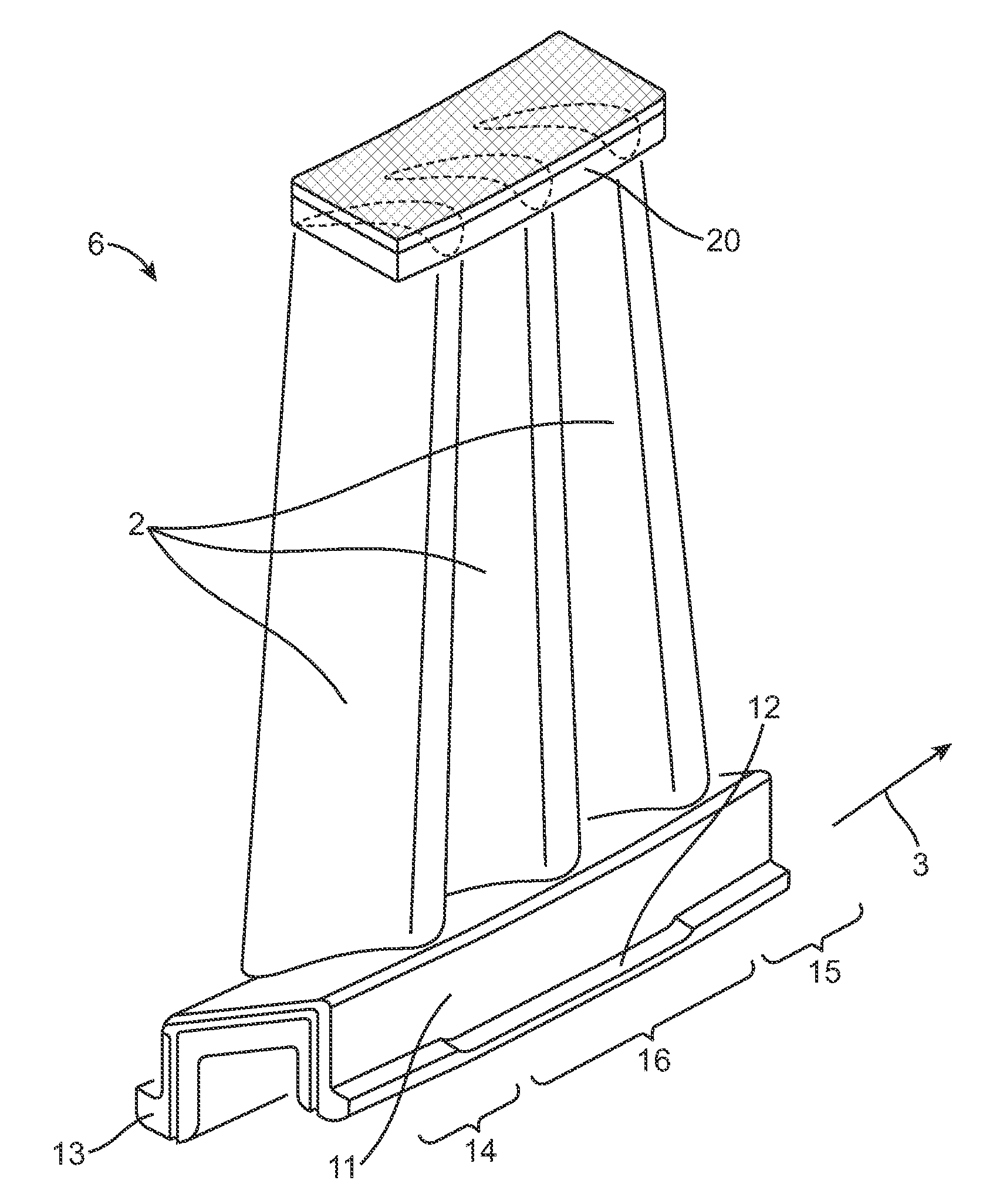
[0024]According to FIG. 1, a guide vane ring 1 of a turbomachine, not otherwise illustrated, preferably of a turbine or compressor, preferably of a gas turbine, possesses a plurality of guide vanes or, in brief, vanes 2 which are arranged adjacently to one another in the circumferential direction 3. The vanes 2 are fastened on a vane carrier 4 which is itself fastened to a casing 5 of the turbomachine.

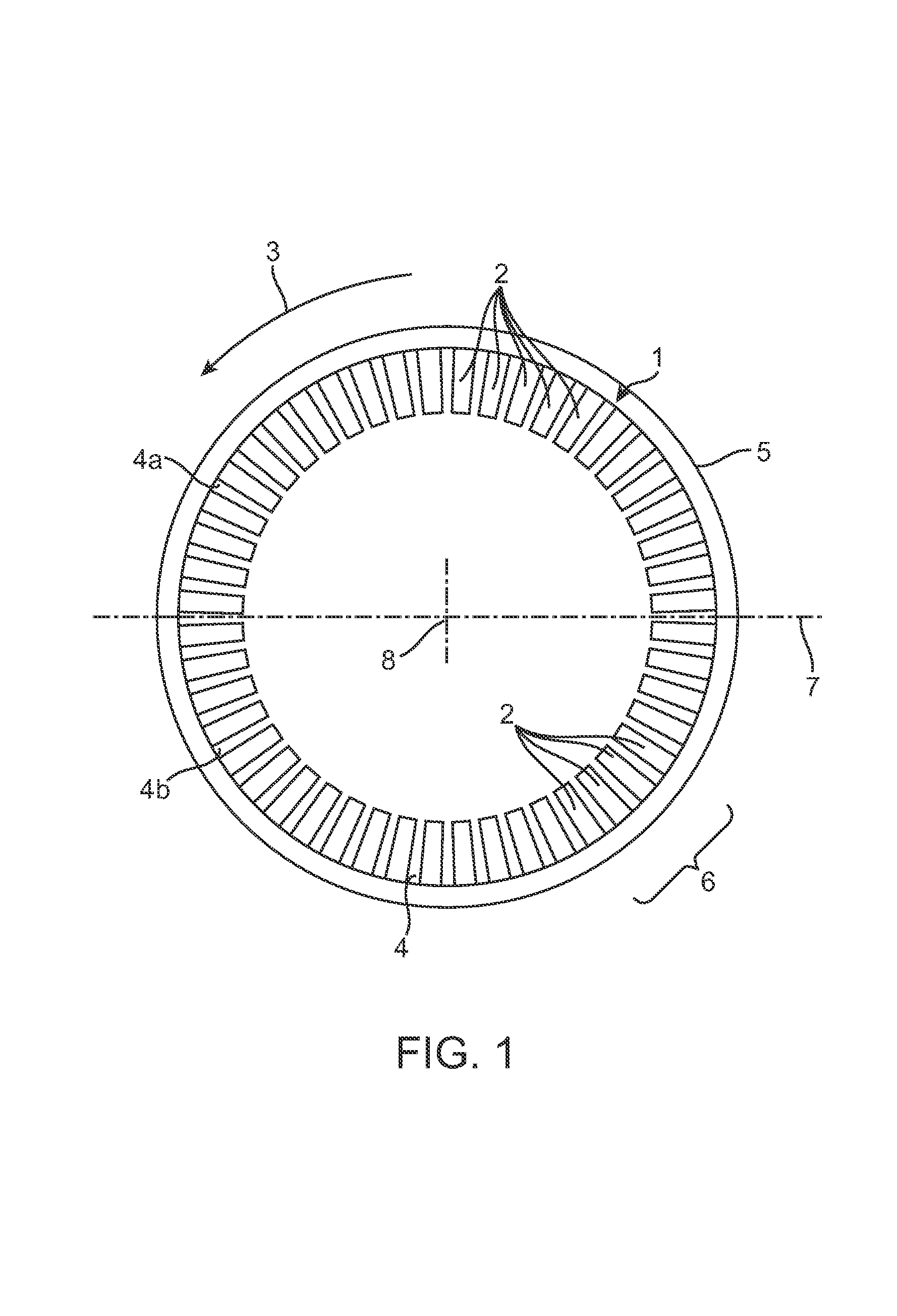
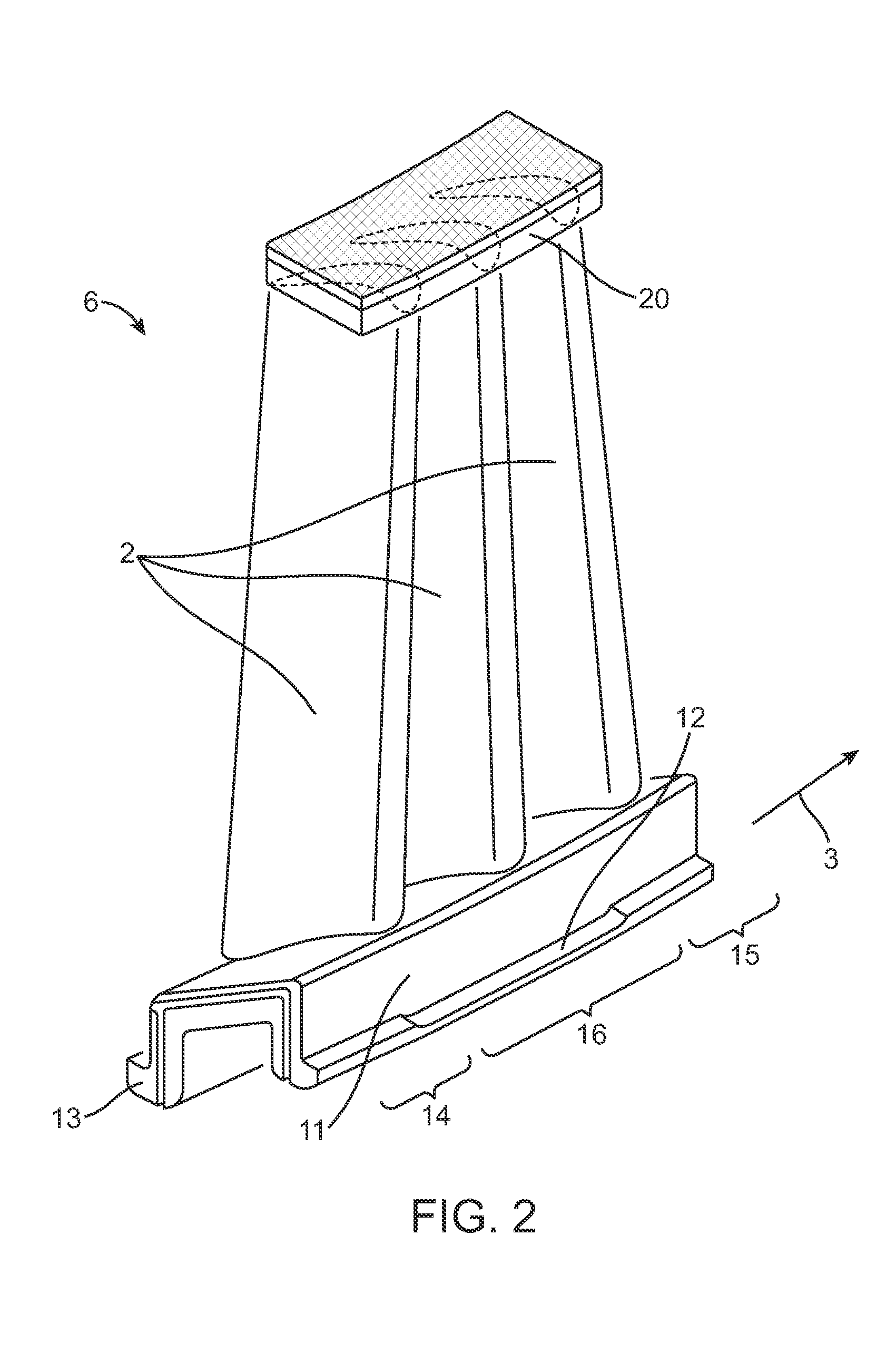
[0025]In this case, the vanes 2 may be fastened individually to the vane carrier 4 or be combined into vane groups 6 which are formed from two or more vanes 2 and are jointly fastened on the vane carrier 4. The vane carrier 4 is in this case of annular design and is expediently divided in the region of a parting plane 7 in which preferably an axis of rotation 8 or longitudinal center axis 8 of the turbomachine also lies, so that, according to FIG. 1, there are an upper vane carrier part 4a and a lower vane carrier part 4b. It is clear that a vane carrier 4 of this type may basically al...


PUM


Abstract

A guide vane ring of a turbomachine, in particular of an axial-throughflow turbine, includes a vane group (6) having a plurality of vanes (2). The vane group (6) has a vane root (11) which has two flanges (12, 13). The vane group (6) is fastened to a vane carrier by means of the flanges (12, 13). In order to reduce stresses in the vanes (2) which occur during deformations of the vane carrier, one flange (13) has on a front end portion (14) and on a rear end portion (15), radially on the inside and radially on the outside, in each case a contact zone (18) which bears against the vane carrier. The other flange (12) has on one end portion (15), radially on the inside, a contact zone (18) which bears against the vane carrier, and is spaced apart from the vane carrier radially on the outside. Moreover, this flange (12) has on the other end portion (14), radially on the outside, a contact zone (18) which bears against the vane carrier, and is spaced apart from the vane carrier radially on the inside. Furthermore, the flanges (12, 13), between their end portions (14, 15), are spaced apart from the vane carrier radially on the inside and radially on the outside.

Description

[0001]This application claims priority under 35 U.S.C. § 119 to Swiss patent application number 01769 / 04, filed 26 Oct. 2004, the entirety of which is incorporated by reference herein.BACKGROUND OF THE INVENTION[0002]1. Field of the Invention[0003]The present invention relates to a guide vane ring of a turbomachine, in particular of an axial-throughflow turbine or a compressor, in particular of a gas turbine. The invention relates, moreover, to a method of a modification of a guide vane ring of this type.[0004]2. Brief Description of the Related Art[0005]A guide vane ring conventionally consists of a plurality of vanes which are arranged next to one another in the circumferential direction and in this case are fastened to an annular vane carrier individually or in groups comprising a plurality of vanes. This vane carrier, which conventionally consists of two semiannular or semicircular parts, is itself fastened to a casing of the turbomachine. Conventionally, the vane carrier for th...

Claims


Application Information

Patent Timeline
Patent Type & Authority Patents(United States)
IPC IPC(8): F01D25/28
CPCF01D9/042F05B2230/606F05D2230/642
Inventor BENEDETTI, BRUNOBOEGLI, ANDREASHULME, CHRISTOPHERRITCHIE, JAMESSCHNEDLER, PATRICK WOLFGANG
Owner ANSALDO ENERGIA IP UK LTD
Why Eureka
Try Eureka