Scroll compressor

a compressor and roller technology, applied in the direction of machines/engines, liquid fuel engines, light and heating apparatus, etc., can solve the problems of deterioration of compression chamber performance, adverse influence of compression efficiency, and increase of leakage in the outer peripheral side compression chamber, so as to enhance sealing ability, avoid performance deterioration, and improve compression chamber performance

Inactive Publication Date: 2008-12-02
PANASONIC CORP
View PDF11 Cites 2 Cited by
  • Summary
  • Abstract
  • Description
  • Claims
  • Application Information

AI Technical Summary

Benefits of technology

[0019]With this aspect, the amount of oil to be supplied to the compression chamber can be controlled by resistance generated when lubricant oil collides against the oil collision part. That is, the suction overheat is minimized, minimum oil as seal oil can be supplied and thus, it is possible to provide an efficient scroll compressor.
[0035]When carbon dioxide refrigerant is used, since the carbon dioxide refrigerant has large pressure difference of compression chamber, performance of compression chamber is deteriorated due to leakage even with slight lack of seal oil, but if the structure of the embodiment is employed, it is possible to avoid the deviation of oil supply, refrigerant and lubricant oil are sufficiently mixed with each other to enhance the sealing ability, and it is possible to avoid the deterioration of performance. Thus, it is possible to provide a scroll compressor using carbon dioxide refrigerant.

Problems solved by technology

However, it is difficult to appropriately supply lubricant oil to the suction space only by reducing the suction resistance as in the scroll compressor described in patent document 1, and the compression efficiency is adversely influenced and its performance is deteriorated.
Therefore, lubricant oil supplied to the compression chamber formed in the outer peripheral direction of the orbiting scroll part becomes insufficient, the leakage in the outer peripheral side compression chamber is increased, and the performance is deteriorated.
If the supply rate of lubricant oil is increased to compensate the oil supply shortage in the outer peripheral direction of the orbiting scroll part, suction overheat is caused and the volumetric efficiency is deteriorated.
At that time, there is a problem that the refrigerant collides against a wall surface or a swirl is formed, pressure loss is generated and the performance is deteriorated.
In the case of the former method, if the narrowed portion 12 is reduced, the possibility that the narrowed portion 12 is closed by contamination is increased, and when the narrowed portion 12 is closed, the lubricant oil is not supplied to the compression chamber 5, galling or abnormal wearing is generated, and the reliability of the compressor is largely deteriorated.
In the case of the latter method, if the set pressure is increased, a force for pushing the orbiting scroll part 4 against the fixed scroll part 2 is abnormally increased at the time of high load operation.
As a result, galling or abnormal wearing is generated in the pushing surface, and the reliability of the compressor is largely deteriorated.
The methods for controlling the supply rate of lubricant oil have such problems.
Thus, there is a problem that pressure loss is generated by swirl generated during the suction process, the suction efficiency is deteriorated, and since the refrigerant and lubricant oil are not sufficiently, leakage loss is increased.
However, since a pressure difference between discharge pressure and suction pressure is about 7 to 10 times higher than that of the conventional refrigeration cycle using CFCs as the refrigerant, small shortage of seal oil increases leakage of compression chamber, and the performance is deteriorated.

Method used


Image

  • Scroll compressor
  • Scroll compressor
  • Scroll compressor

Examples


first embodiment

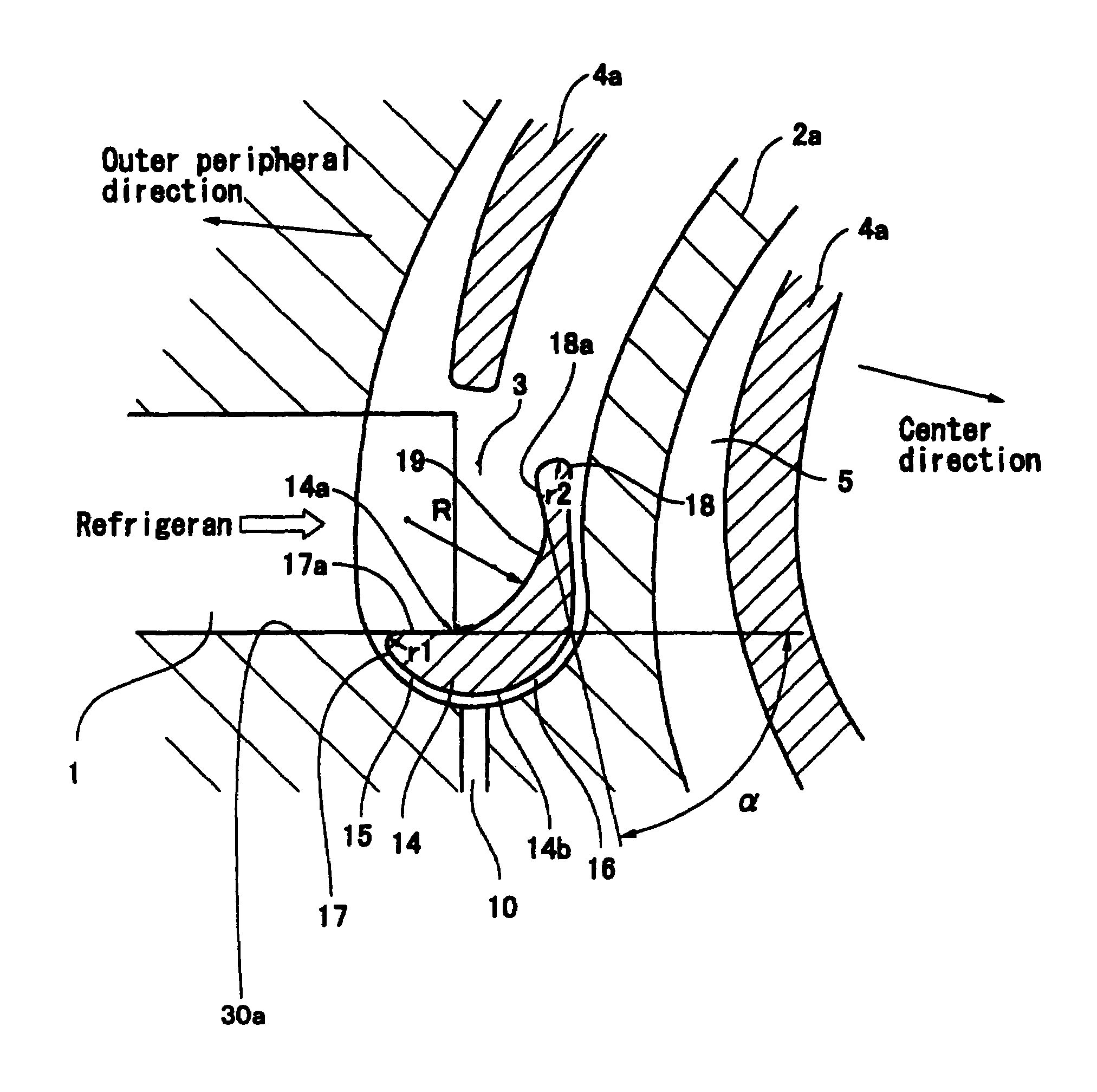
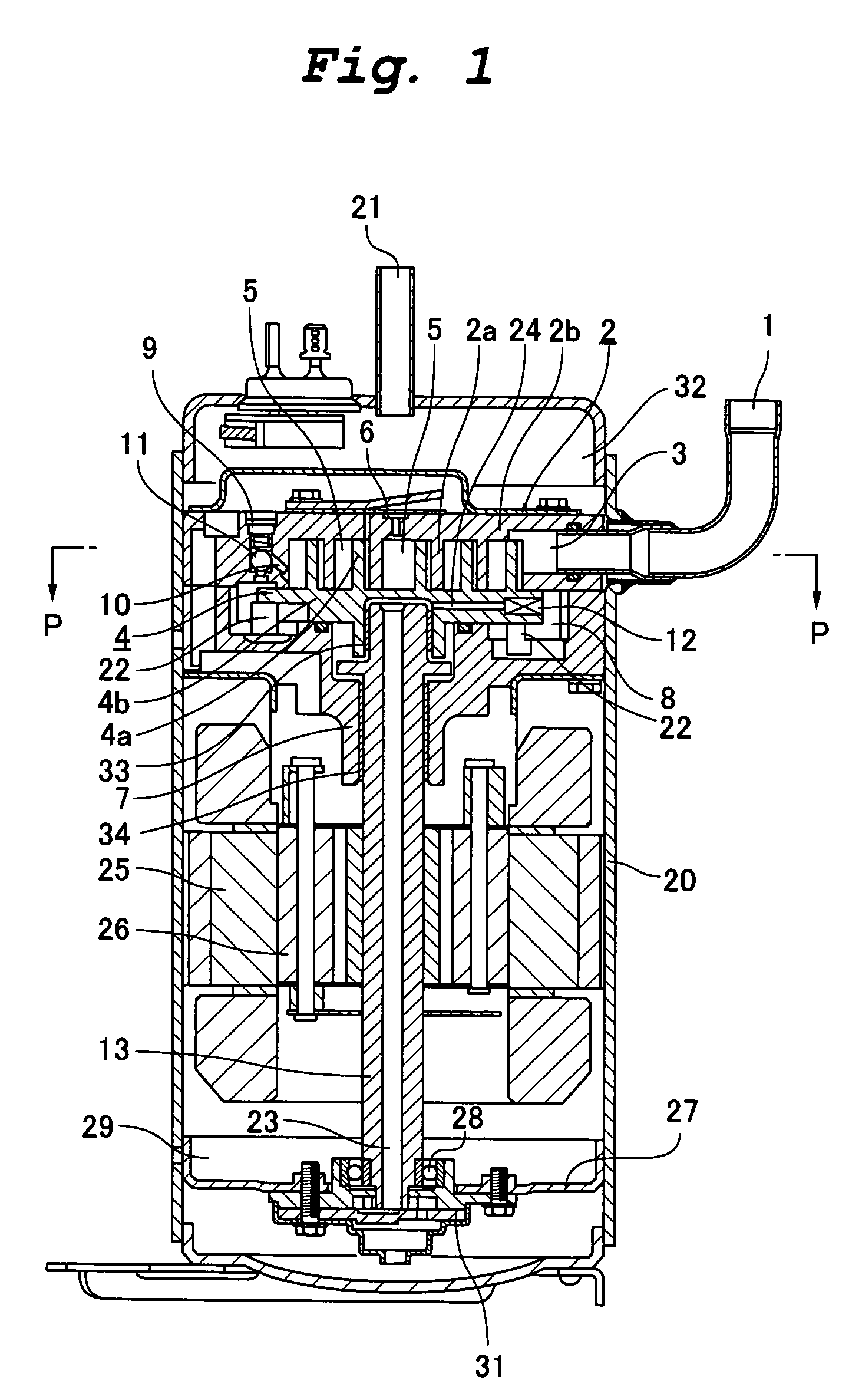
[0042]FIG. 1 is a sectional view showing a scroll compressor of a first embodiment of the present invention. The same members as those of the conventional scroll compressor shown in FIG. 4 are designated with the same symbols.

[0043]The scroll compressor of the embodiment includes a compressor mechanism and a motor mechanism in a container 20. The compressor mechanism is disposed at an upper portion in the container 20, and the motor mechanism is disposed below the compressor mechanism. The container 20 is provided at its upper portion with a suction pipe 1 and a discharge pipe 21. An oil reservoir 29 for accumulating lubricant oil is provided at a lower portion in the container 20.

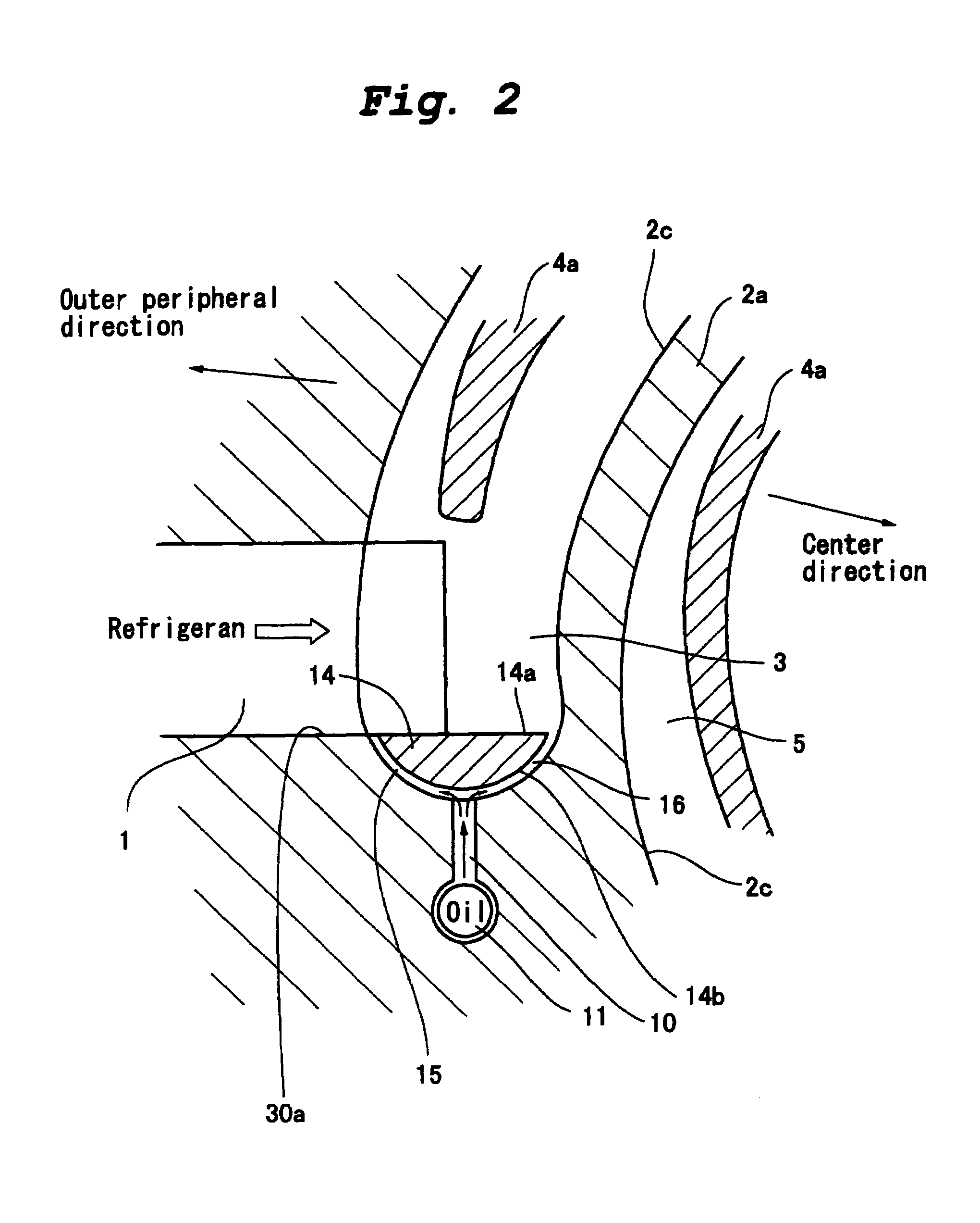
[0044]The compressor mechanism includes a fixed scroll part 2 and an orbiting scroll part 4. The fixed scroll part 2 and the orbiting scroll part 4 are meshed with each other to form a plurality of compression chambers 5. The fixed scroll part 2 has a scroll lap 2a rising from a mirror plate 2b, and the or...


PUM

PropertyMeasurementUnit
rotation frequencyaaaaaaaaaa
suction pressureaaaaaaaaaa

Abstract

According to the present invention, an oil supply passage is formed in a suction space of a fixed scroll part, and an oil collision part is provided in the suction space. The oil collision part is provided in the suction space, an amount of oil to be supplied is controlled, refrigerant and lubricant oil are sufficiently mixed with each other. Tangents of ends of the oil collision part are made acute angle to smoothen the flow of the refrigerant.

Description

TECHNICAL FIELD[0001]The present invention relates to a scroll compressor in which a fixed scroll part and an orbiting scroll part are meshed with each other to form a compression chamber, the orbiting scroll part is allowed to orbit to carry out suction, compression and discharge while continuously changing a capacity of the compression chamber.BACKGROUND TECHNIQUE[0002]As a refrigeration or air conditioning hermetic compressor, there are conventional reciprocating type, rotary type and scroll type compressors, and these compressors are used in refrigeration or air conditioning fields of domestic or business purpose. Currently, compressors are developed while utilizing characteristics in terms of costs and performance.[0003]Among them, a so-called hermetical compressor for preventing noise and eliminating the need of maintenance is a typical compressor in which a compressor mechanism and a motor are accommodated in a container, and a scroll compressor and a rotary compressor are in...

Claims


Application Information

Patent Timeline
Patent Type & Authority Patents(United States)
IPC IPC(8): F04C18/04C09K5/04F04C18/02F04C23/00F04C29/02F25B1/04
CPCF04C18/0215F04C23/008F04C29/028F04C18/02F04C29/02
Inventor HIWATA, AKIRAMORIMOTO, TAKASHIFUTAGAMI, YOSHIYUKIIIDA, NOBORUSAWAI, KIYOSHI
Owner PANASONIC CORP
Why Eureka
Try Eureka