
Auxiliary oil pump integrated with a vehicle transmission

a technology of auxiliary oil pump and vehicle transmission, which is applied in the direction of pump, positive displacement liquid engine, machine/engine, etc., can solve the problem that the stop/start function usually requires significant changes to the transmission, and achieve the effect of minimizing the inlet suction head

Active Publication Date: 2015-12-08
FORD GLOBAL TECH LLC
View PDF12 Cites 1 Cited by
  • Summary
  • Abstract
  • Description
  • Claims
  • Application Information

AI Technical Summary

Benefits of technology

This configuration ensures reliable operation of the auxiliary oil pump, maintaining pressure in friction elements and facilitating the stop-start engine function with minimal modifications to the transmission, enhancing fuel efficiency and reducing installation complexity.

Problems solved by technology

Adding the electric motor and oil pump to an automatic transmission to support the stop / start function usually requires significant changes to the transmission.

Method used


Image

  • Auxiliary oil pump integrated with a vehicle transmission
  • Auxiliary oil pump integrated with a vehicle transmission
  • Auxiliary oil pump integrated with a vehicle transmission

Examples


Embodiment Construction

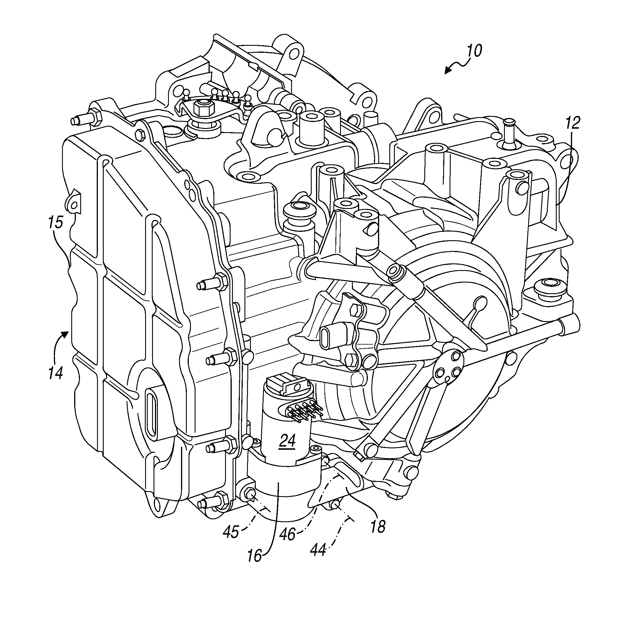
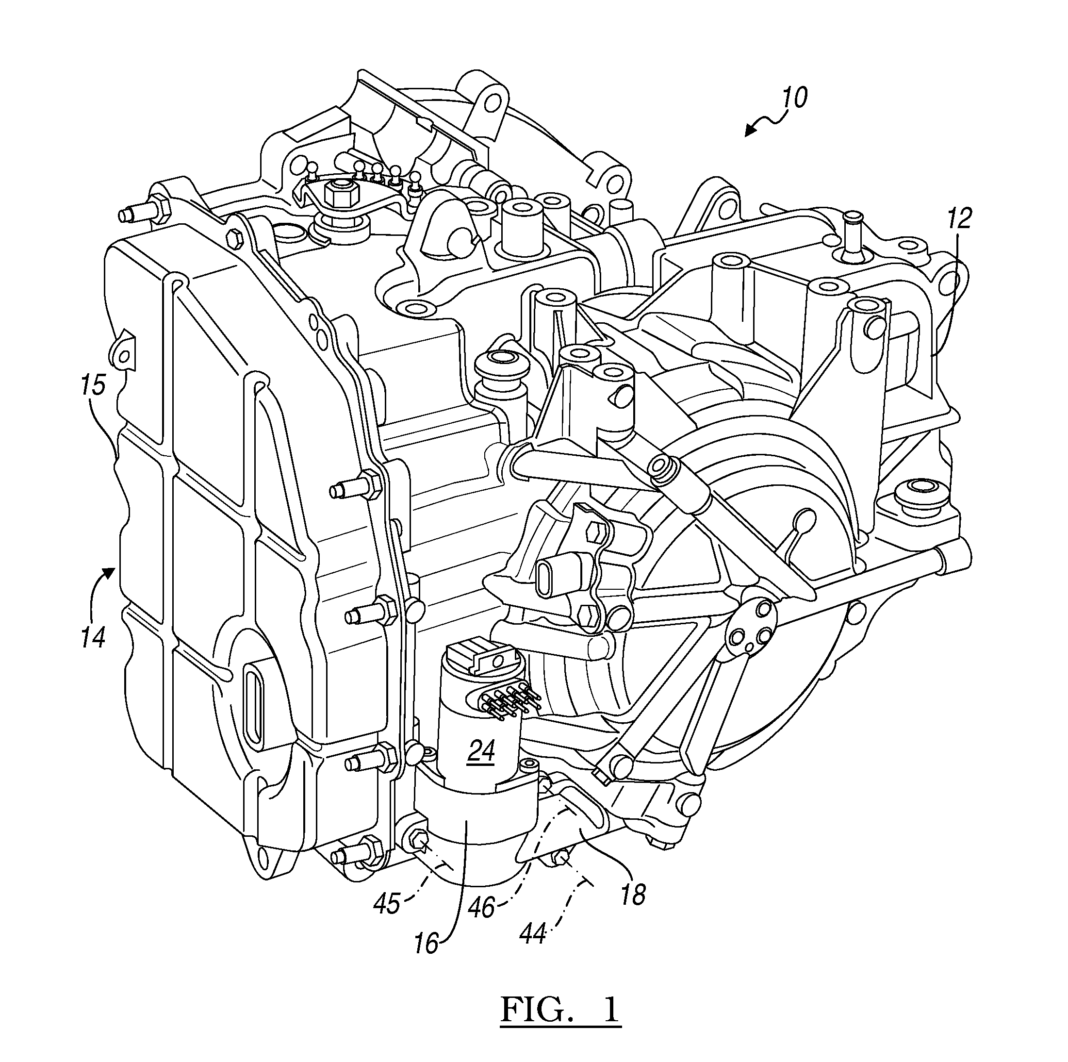
[0019]Referring now to the drawings, there is illustrated in FIGS. 1 and 2 a transaxle assembly 10, case 12 enclosing a torque converter, gearing and hydraulically actuated clutches and brakes, which control the gearing. A valve body 14 comprising hydraulic valves, solenoids and passages interconnecting the components is enclosed in case 12, and covered by a cover 15, secured to a front surface of the case 12.

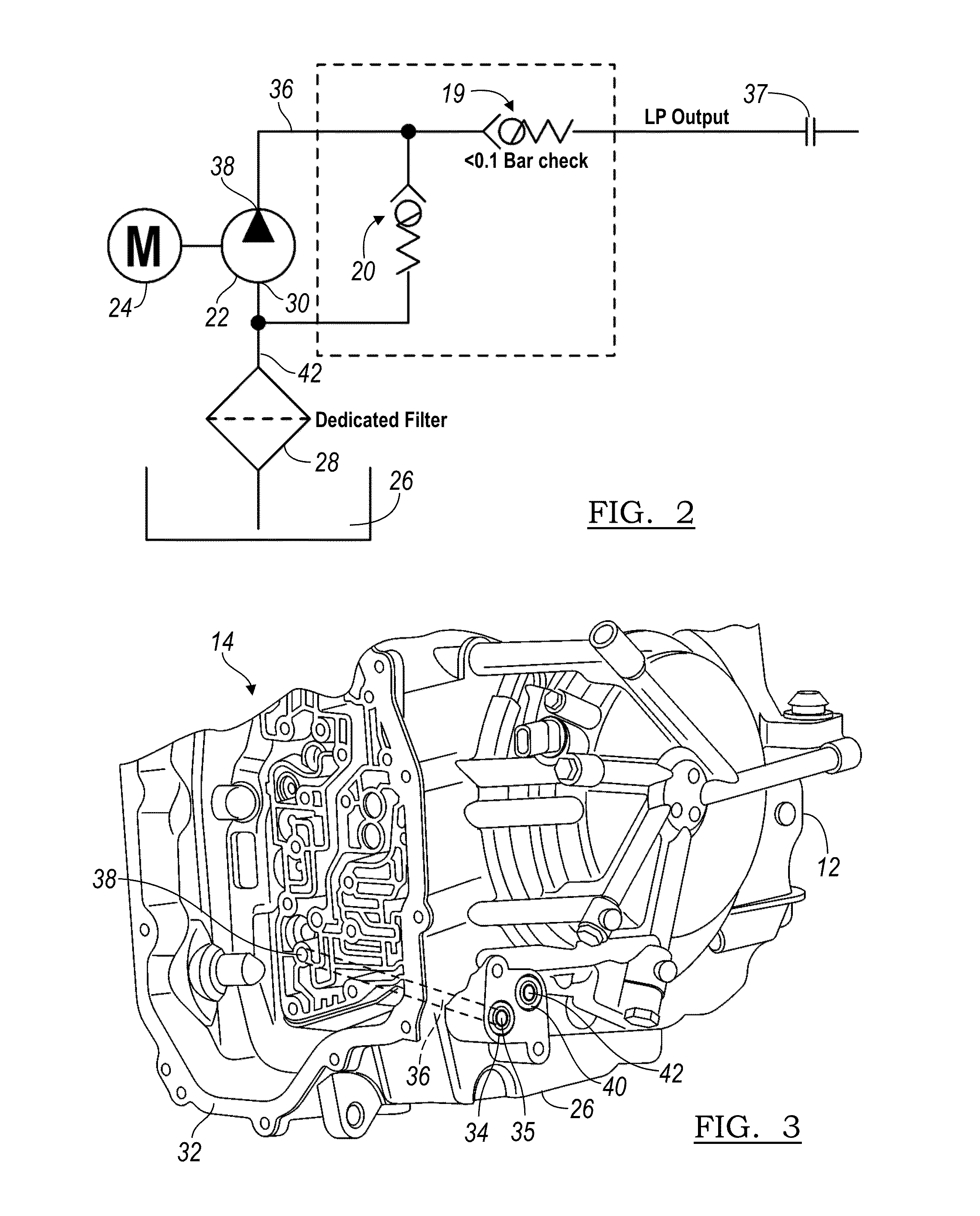
[0020]An auxiliary oil pump assembly 16 is mounted on the upper surface of a manifold 18, which contains a check valve 19 and pressure relief valve 20. The manifold 18 and pump assembly 16 are mounted at a low elevation on the transaxle case 12 and external to the case 12 and at substantially the same elevation as oil sump 26. Preferably the pump 22 of the pump assembly 16 is a G-rotor pump, although a vane pump or another suitable pump type can be used.

[0021]Pump 22 is driven by an electric motor 24, preferably a brushless DC motor, which is powered by an electric storage batt...


PUM


Abstract

An assembly for an automotive vehicle transmission includes a case containing a fluid sump and valve body, a pump supported on the case, a passage formed in the case for carrying fluid from the pump to a transmission control element, and a second passage formed in the case for carrying fluid from the oil sump to the pump.

Description

BACKGROUND OF THE INVENTION[0001]1. Field of the Invention[0002]This invention relates generally to an automatic transmission for motor vehicle, and, more particularly, to integrating an auxiliary oil pump, electric drive system and the hydraulic control and supply circuit of the transmission.[0003]2. Description of the Prior Art[0004]An electrical starting motor is used to crank and start an engine in an automotive vehicle equipped with an automatic transmission. To improve vehicle fuel economy, a stop-start engine cranking system automatically turns the engine off when the accelerator pedal is released, the brake pedal is depressed and the vehicle speed is substantially zero for a predetermined period, provided the state of charge of a battery that powers the starting motor is sufficiently high. The engine cranking system automatically restarts the engine in response to the vehicle operator's releasing the brake pedal and depressing the accelerator pedal, indicating a desire to ac...

Claims


Application Information

Patent Timeline
Patent Type & Authority Patents(United States)
IPC IPC(8): F16H57/02F04B17/03F16H61/00
CPCF16H61/0009F16H61/0021F16H2061/0046Y10T74/2186
Inventor FRAIT, STEVEN A.DEUTSCH, LAURENCE A.PRABHU, SENTHIL
Owner FORD GLOBAL TECH LLC
Learn More