Inducer for centrifugal pump

a centrifugal pump and inducer technology, applied in the direction of non-positive displacement fluid engines, radial flow pumps, non-positive displacement pumps, etc., can solve the problems of fluid not moving up through the inducer as efficiently, beg to rotate, and change in pressure near, so as to increase the npsh

Active Publication Date: 2017-04-25
ELLIOTT CO
View PDF24 Cites 2 Cited by
  • Summary
  • Abstract
  • Description
  • Claims
  • Application Information

AI Technical Summary

Benefits of technology

[0026]The present invention is a variation and improvement on the configuration of inducer blades or vanes that are based on helicoid plane surface for use in vertical flow inducers. One object and advantage of the present invention is to reduce rotational momentum, increase upward flow of the liquid medium and consequently minimizes the net positive suction head required [NPSHR].
[0027]The present invention is also an inducer with improved helicoid blades in combination of an inducer housing that incorporates grooves or vanes that are helical in nature and in counter-rotation with respect to the rotation of the blades of the inducer, which grooves or vanes capture fluid rotating with the inducer blades and use that rotation to move the fluid up along the grooves or vanes and into an impeller of a centrifugal pump or other device.
[0028]The present invention is also a multi-stage inducer system that combines a rotating inducer and a non-rotating inducer. The non-rotating inducer portion use the rotational momentum of the fluid generated by the rotating inducer portion to progress the fluid forward while removing the rotational momentum, thereby increasing the NPSH.
[0029]Further details, objects and advantages of the present invention will become apparent through the following descriptions, and will be included and incorporated herein.

Problems solved by technology

A common problem with spiral or helical inducers used within centrifugal pumps and similar devices is that the fluid in the tank in which the centrifugal pump is installed will begin to rotate in the same direction as, and along with, the inducer blades.
When this occurs, the fluid does not move up through the inducer as efficiently.
This phenomenon can also result in a change in pressure near the inlet of the inducer and increase the amount of net positive suction head required [NPSHR] to make the pump continue to work efficiently or properly.
In addition, cavitation causes noise, vibration, and erosion of material from the device.
Thus, the service life of a pump can be shortened due to cavitation.
While grooves have been used in inducer designs in the past, they have not been used to help efficiently move the fluid through the inducer.
Okamura et al. acknowledge, however, that increasing the specific speed of mixed-flow pumps has a tendency to make their performance curves unstable and to cause a big hump at low capacities, thus it is stated that it is doubtful that the illustrated technique would be effective for higher specific-speed, i.e., higher flow rate pumps.

Method used


Image

  • Inducer for centrifugal pump
  • Inducer for centrifugal pump
  • Inducer for centrifugal pump

Examples


Embodiment Construction

[0048]The description that follows is presented to enable one skilled in the art to make and use the present invention, and is provided in the context of a particular application and its requirements. Various modifications to the disclosed embodiments will be apparent to those skilled in the art, and the general principals discussed below may be applied to other embodiments and applications without departing from the scope and spirit of the invention. Therefore, the invention is not intended to be limited to the embodiments disclosed, but the invention is to be given the largest possible scope which is consistent with the principals and features described herein.

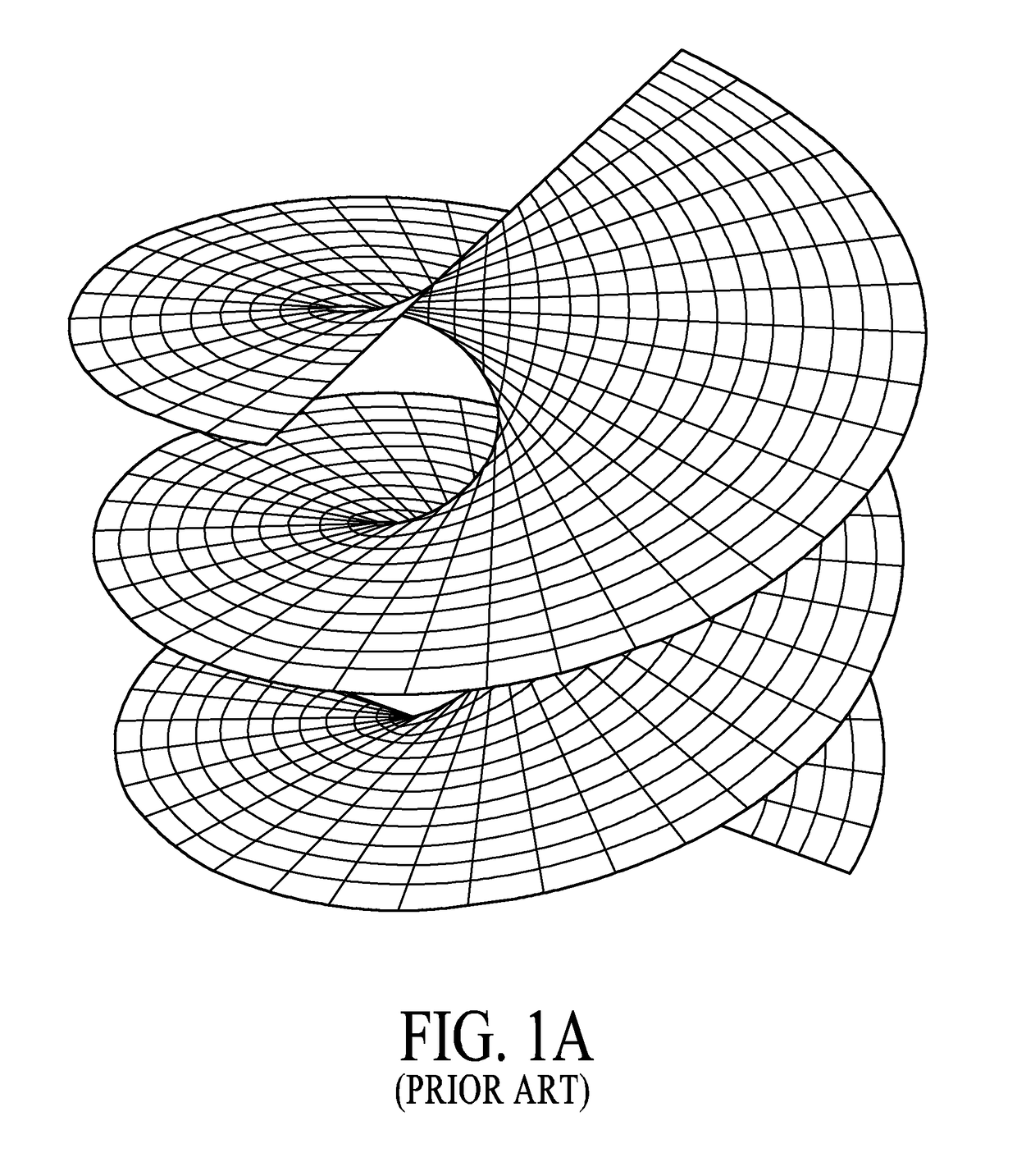
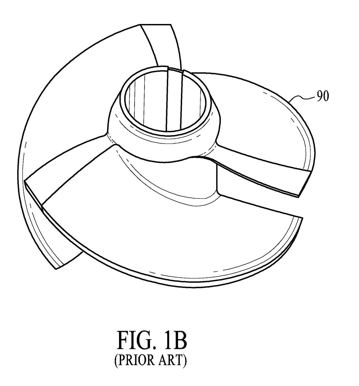
[0049]It is common for inducer blades to be constructed strictly following the helicoid plane surface configuration, as best shown in FIG. 1C. As shown in FIG. 1D, in the presence of a vertical bisecting plane 70, it is easy to see that the intersection between the helicoid plane surface and a vertical bisecting plan on the ...


PUM


Abstract

An inducer for vertical flow, cryogenic liquid centrifugal pumps comprising a stationary outer housing portion having an inlet and an outlet, the inlet located at a lower end and the outlet located at an upper end, the housing further having an inner wall portion with one or more spiral vanes projecting outwardly from the inner wall portion, the one or more spiral vanes defining one or more gap regions on the inner wall portion that spiral in a first direction, and an inner rotating impeller mounted on a rotating center shaft, the impeller having at least one curved blade which defines a curved, helicoid plane surface in which the slope of the plane increases as the distance from the center axis increases, the impeller rotating in a second direction which is in counter rotation to the first direction.

Description

RELATED APPLICATIONS[0001]This application is a Divisional Patent Application of U.S. patent application Ser. No. 12 / 903,128 filed Oct. 12, 2010 entitled “INDUCER FOR CENTRIFUGAL PUMP”, which is a Nonprovisional Patent Application of U.S. Provisional Patent Application Ser. No. 61 / 278,666 filed Oct. 9, 2009 entitled “INDUCER FOR CENTRIFUGAL PUMP”, which is incorporated herein by reference in its entirety, and claims any and all benefits to which it is entitled therefrom.FIELD OF THE INVENTION[0002]The present invention pertains to a noncavitating inducer for cryogenic centrifugal pump, and more specifically, to a unique inducer blade / vane design and configuration and inducer system for enhancing centrifugal pump efficiency and decreasing the net positive suction head required (NPSHR) for proper pump operation.BACKGROUND OF THE INVENTION[0003]FIG. 1A (prior art) is a representative view showing a partial plot of the helicoid plane known heretofore.[0004]FIG. 1B (prior art) is a repre...

Claims


Application Information

Patent Timeline
Patent Type & Authority Patents(United States)
IPC IPC(8): F04D1/06F04D29/22F04D7/02F04D29/44
CPCF04D7/02F04D29/2277F04D29/445
Inventor KILKENNY, EVERETT RUSSELL
Owner ELLIOTT CO
Why Eureka
Try Eureka