Eureka AIR delivers breakthrough ideas for toughest innovation challenges, trusted by R&D personnel around the world.

High-pressure discharge lamp with improved discharge vessel structure

Inactive Publication Date: 2008-12-02
PATENT TREUHAND GESELLSCHAFT FUR ELECTRIC GLUEHLAMPEN MBH
View PDF13 Cites 0 Cited by
  • Summary
  • Abstract
  • Description
  • Claims
  • Application Information

AI Technical Summary

Benefits of technology

[0003]It is the object of the invention to provide a generic high-pressure discharge lamp having an extended life.
[0008]FIG. 5 shows the fact that the high-pressure discharge lamps having a larger volume filled by the discharge vessel material in the above-defined central section and under otherwise identical conditions have a lower temperature on the top of the discharge vessel. Owing to the horizontal lamp operation, i.e. with electrodes arranged on the horizontal plane, the hottest point on the discharge vessel is on its top side. The illustrations in FIGS. 4 and 5 ensure a longer life for the high-pressure discharge lamps according to the invention owing to the comparatively high relative luminous flux and the reduced thermal load on the discharge vessel.
[0011]The discharge vessel of the high-pressure discharge lamps according to the invention is preferably made from quartz glass, i.e. the content by weight of silicon dioxide in the material of the discharge vessel is at least 99 percent by weight. Quartz glass withstands the high operating temperature, the high-pressure and the chemical attack of the ionizable filling. Quartz glass has the advantage over a light-transmissive ceramic, which also offers the abovementioned advantages, that in the case of discharge vessels made from quartz glass it is easier to seal the current feedthroughs.

Problems solved by technology

High-pressure discharge lamps having a residual luminous flux below 70 percent of their initial luminous flux have a life expectancy which is too low.

Method used


Image

  • High-pressure discharge lamp with improved discharge vessel structure
  • High-pressure discharge lamp with improved discharge vessel structure
  • High-pressure discharge lamp with improved discharge vessel structure

Examples


Embodiment Construction

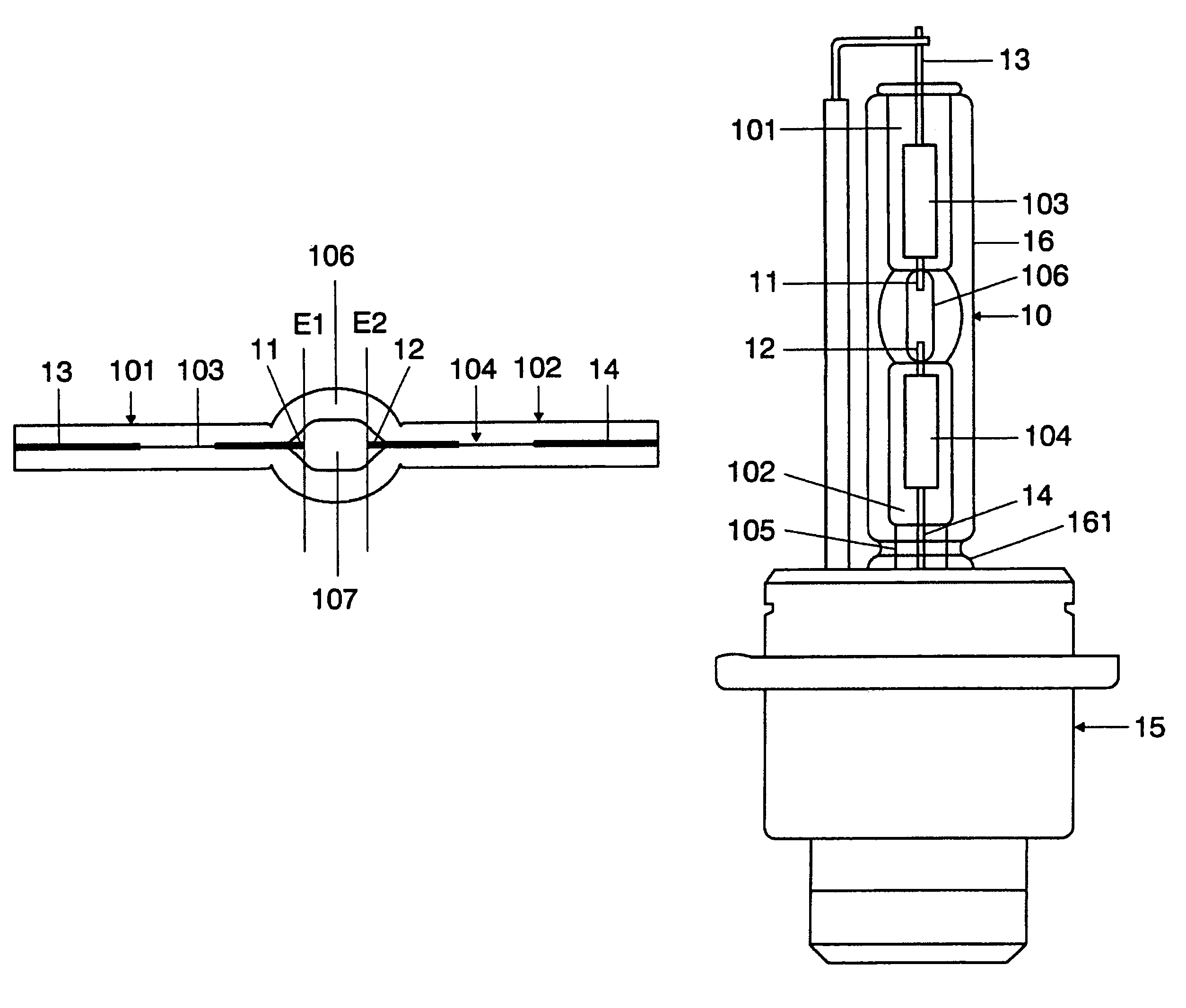
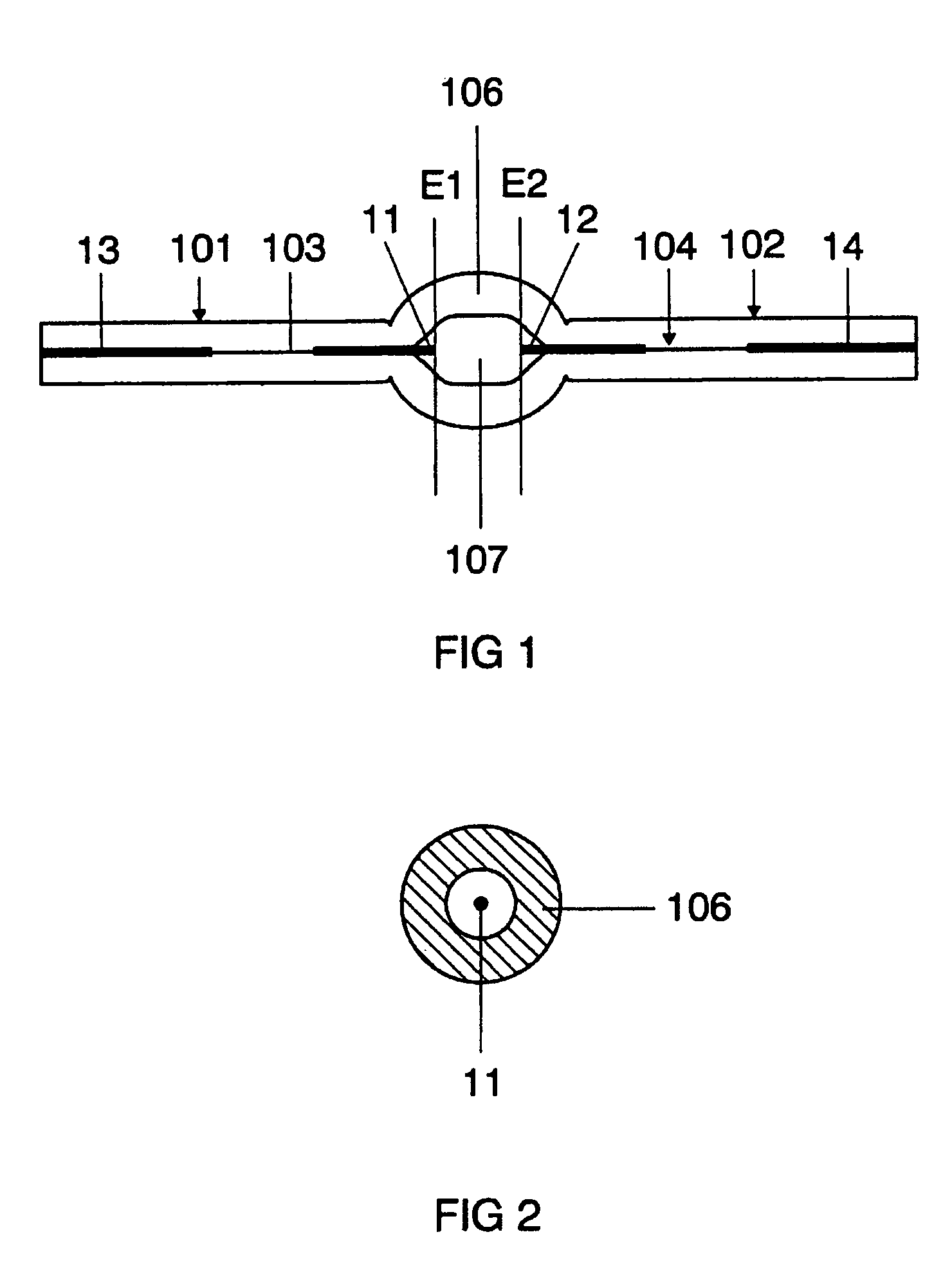
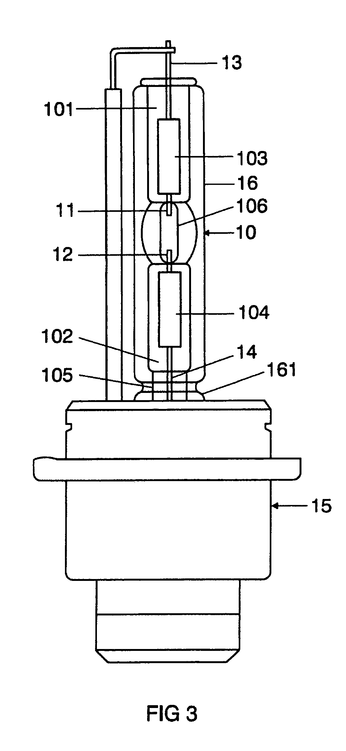
[0019]FIG. 3 is a schematic illustration of a high-pressure discharge lamp in accordance with the preferred exemplary embodiment of the invention. Of concern here is a halogen metal-vapor high-pressure discharge lamp having a power rating of 35 watts. This lamp is envisaged for use in a vehicle headlight. It has a discharge vessel 10 which is sealed at two ends and is made from quartz glass, whose interior 107 has a volume of 22.5 mm3, and in which an ionizable filling is enclosed in a gas-tight manner. In the central section 106 of the discharge vessel 10, the inner contour of the discharge vessel 10 is circular-cylindrical and its outer contour corresponds essentially to that of a circular barrel body, i.e. the outer contour is produced by rotation of a circular arc around the discharge vessel axis. The inner diameter of the central section 106 is 2.6 mm, and its largest outer diameter is 6.3 mm. The two ends 101, 102 of the discharge vessel 10 are each sealed by means of a fused ...


PUM


Abstract

A high-pressure discharge lamp for a vehicle headlight having a discharge vessel and electrodes arranged therein for the purpose of generating a gas discharge, the discharge vessel having a central section which is delimited by two planes which are arranged perpendicularly to the connection path of the discharge-side ends of the electrodes and each extend through the discharge-side end of one of the electrodes, wherein the volume, which is arranged in said central section and is filled by the material of the discharge vessel, is greater than or equal to 95 mm3.

Description

I. TECHNICAL FIELD[0001]The invention relates to a high-pressure discharge lamp for a vehicle headlight having a discharge vessel and electrodes arranged therein for the purpose of generating a gas discharge, the discharge vessel having a central section which is delimited by two planes which are arranged perpendicularly to the connection path of the discharge-side ends of the electrodes and each extend through the discharge-side end of one of the electrodes.II. BACKGROUND ART[0002]Such a high-pressure discharge lamp is disclosed, for example, in the laid-open specification EP 0 374 676 A2. This specification describes a high-pressure discharge lamp for a vehicle headlight having a discharge vessel made from quartz glass and an ionizable filling which comprises metal halides and xenon.III. DISCLOSURE OF THE INVENTION[0003]It is the object of the invention to provide a generic high-pressure discharge lamp having an extended life.[0004]This object is achieved according to the inventio...

Claims


Application Information

Patent Timeline
IPC IPC(8): H01J17/16H01J61/30
CPCH01J61/30H01J61/827H01J61/073
Inventor GRUNDMANN, DIRKSCHIMKE, CONRAD
Owner PATENT TREUHAND GESELLSCHAFT FUR ELECTRIC GLUEHLAMPEN MBH
Why Eureka
Eureka Blog
Learn More