Methods for determining refractive corrections from wavefront measurements

a wavefront measurement and refractive correction technology, applied in the field of vision correction systems, can solve the problems of not necessarily leading to the best image quality, difficult use of wavefront measurements for refractive correction, and inability to accurately determine the strehl ratio, etc., to achieve the effect of enhancing the accuracy and efficacy of laser eye surgery procedures and being easily adapted for us

Active Publication Date: 2008-12-02
AMO MFG USA INC
View PDF24 Cites 32 Cited by
  • Summary
  • Abstract
  • Description
  • Claims
  • Application Information

AI Technical Summary

Benefits of technology

[0009]The present invention generally provides improved methods and devices for determining refractive corrections from measurements of optical error, such as wavefront measurements. The invention is particularly useful for enhancing the accuracy and efficacy of laser eye surgical procedures such as photorefractive keratectomy (PRK), phototherapeutic keratectomy (PTK), laser in situ keratomileusis (LASIK), and the like, and can be easily adapted for use with existing laser systems. Although methods and systems of the invention are described in the context of laser eye surgery, however, it should be understood the methods and systems may be adapted for use in alternative eye treatment procedures and systems such as for use in radial keratotomy, intraocular lenses, corneal ring implants, and the like.

Problems solved by technology

When an eye has a significant quantity of high-order aberrations, however, minimizing the wavefront RMS does not necessarily lead to best image quality.
This large variation in refractive corrections, depending on the pupil size, contradicts the results seen in clinical refraction and can make the use of wavefront measurements for determining refractive corrections difficult.
Thus, the Strehl Ratio may include information which is not helpful for refractive correction determination.

Method used


Image

  • Methods for determining refractive corrections from wavefront measurements
  • Methods for determining refractive corrections from wavefront measurements
  • Methods for determining refractive corrections from wavefront measurements

Examples


Embodiment Construction

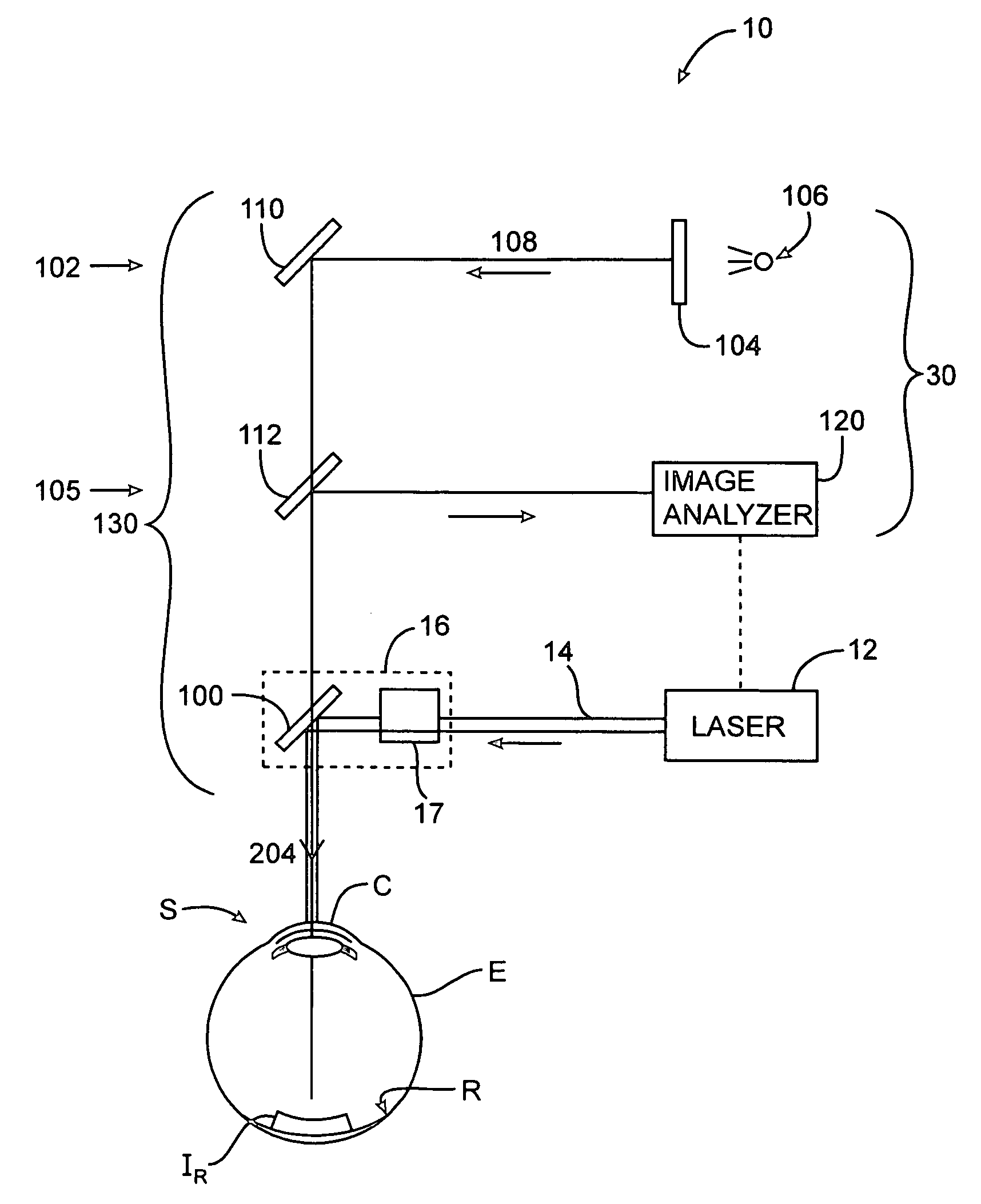
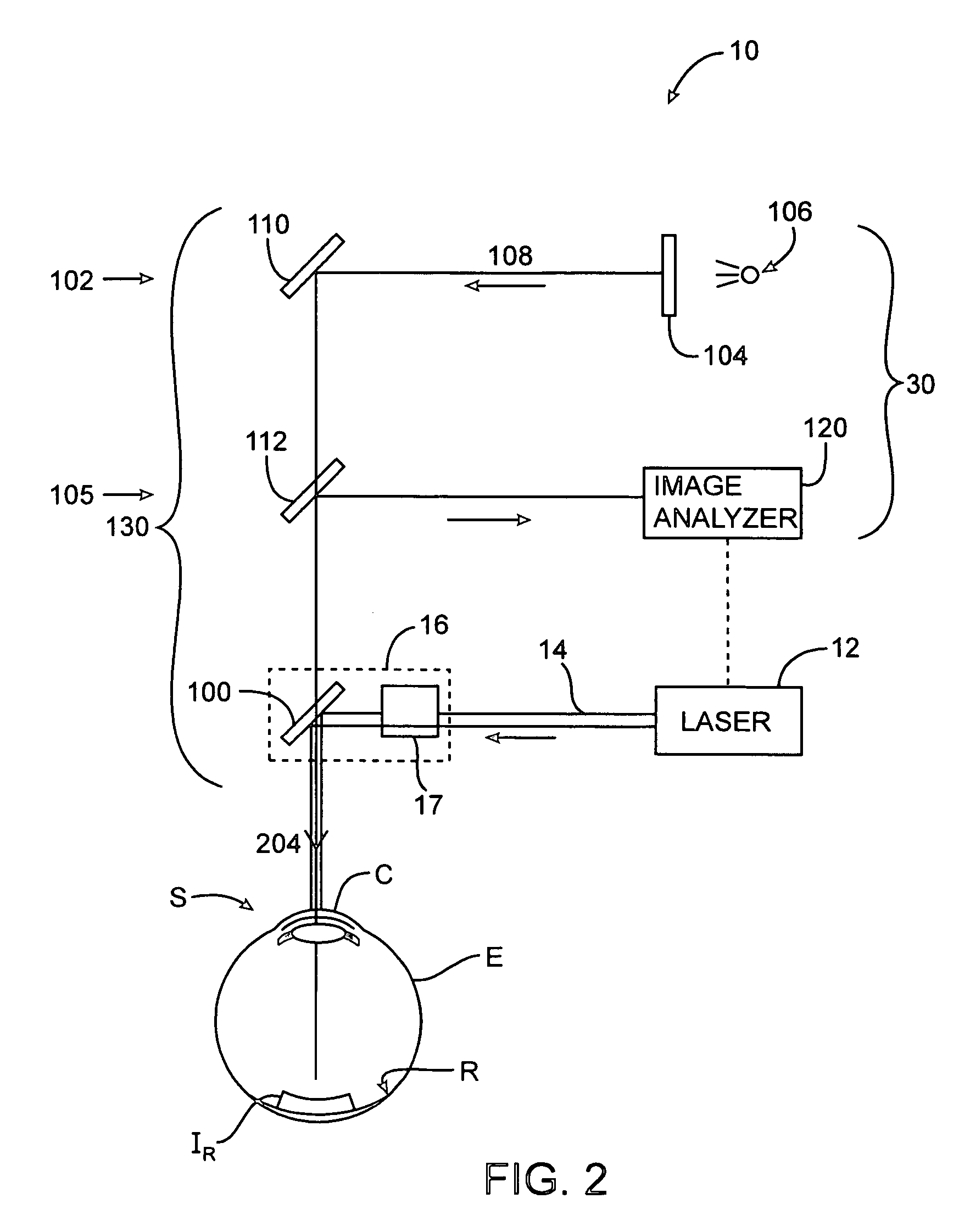
[0029]The present invention generally provides improved methods and devices for determining refractive corrections from measurements of optical error, such as wavefront measurements. The invention is particularly useful for enhancing the accuracy and efficacy of laser eye surgical procedures such as photorefractive keratectomy (PRK), phototherapeutic keratectomy (PTK), laser in situ keratomileusis (LASIK), and the like, and can be easily adapted for use with existing laser systems. Although methods and systems of the invention are described in the context of laser eye surgery, however, it should be understood the methods and systems may be adapted for use in alternative eye treatment procedures and systems such as for use in radial keratotomy, intraocular lenses, corneal ring implants, and the like. All references referred to in this application are hereby incorporated herein by reference.

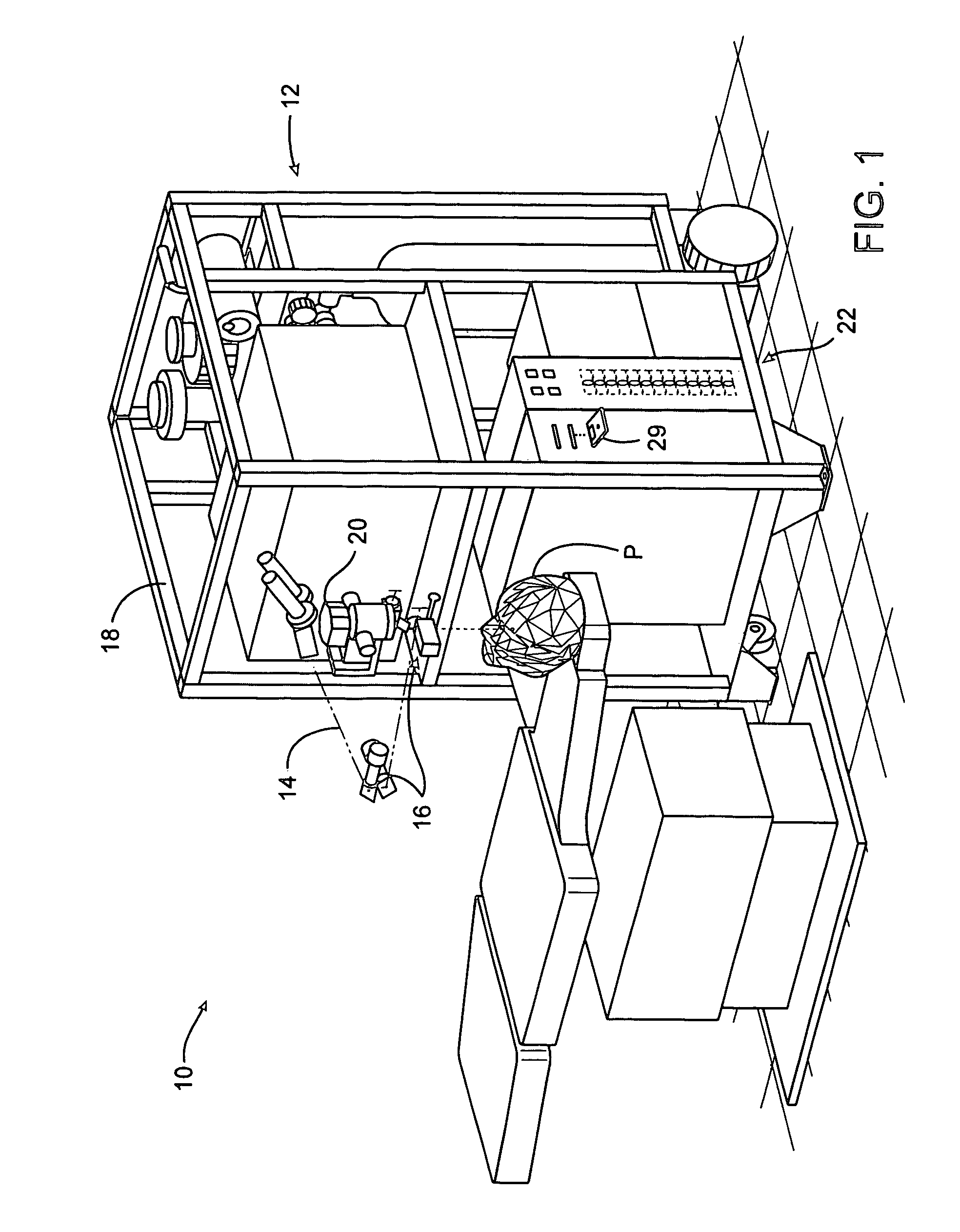
[0030]Referring now to FIG. 1, a laser eye surgery system 10 which may make use of methods and / ...


PUM


Abstract

A method for determining a refractive correction for an eye involves measuring an optical error of the eye, calculating at least one image quality parameter for a selected spatial frequency of range of spatial frequencies, based on the measured optical error of the eye, and forming a plan for refractive correction of the optical error, based on the calculated image quality parometer. In some embodiments, measuring the optical error involves taking one or more wavefront measurements. In some embodiments, calculating the parameter involves calculation a modulation transfer function.

Description

CROSS REFERENCE TO RELATED APPLICATIONS[0001]This application claims the benefit of U.S. Provisional Patent Application No. 60 / 431,622, filed Dec. 6, 2002, entitled “Methods For Determining Refractive Corrections From Wavefront Measurements,” which is hereby fully incorporated by reference.BACKGROUND OF THE INVENTION[0002]The present invention generally relates to vision correction systems. More particularly, the invention relates to improved methods and systems for determining refractive corrections from wavefront measurements.[0003]Laser eye surgical systems typically employ a system that can track and measure optical characteristics of a patient's eye. One promising eye measurement system uses wavefront technology that allows a surgeon to measure and treat low order and high order aberrations in and on the patient's eye. Wavefront measurement of the eye creates a high order aberration map that permits assessment of aberrations throughout the optical pathway of the eye, e.g., both...

Claims


Application Information

Patent Timeline
Patent Type & Authority Patents(United States)
IPC IPC(8): A61B3/10A61B3/14A61B3/103A61F9/01
CPCA61B3/1015A61F9/00806A61F9/00812A61F9/00819A61F2009/00842A61F2009/00848A61F2009/00853A61F2009/00872A61F2009/00897
Inventor LIANG, JUNZHONG
Owner AMO MFG USA INC
Why Eureka
Try Eureka