
Scanning system

a scanning system and scanning technology, applied in the field of scanning systems, can solve the problems of increasing power consumption of the drive means and consuming power of the drive means, and achieve the effect of reducing the load on the drive means

Inactive Publication Date: 2008-12-09
FUJIFILM HLDG CORP +1
View PDF4 Cites 0 Cited by
  • Summary
  • Abstract
  • Description
  • Claims
  • Application Information

AI Technical Summary

Benefits of technology

The present invention provides a scanning system that can move a mobile body with a light source to scan a radiation image recording medium with reduced power consumption. The system includes a holder means to hold the mobile body in a predetermined position, which reduces the load on the drive means and reduces power consumption while the mobile body is waiting to be moved. The technical effect is to improve the efficiency and accuracy of the scanning system.

Problems solved by technology

Accordingly, there has been a problem that the drive means consumes power even if the mobile body is waiting.
The power consumption of the drive means is increased as the direction in which the mobile body is moved approaches the vertical.
Further, it is not preferred from the viewpoint of generation of heat to drive the drive means, such as the linear motor, for a long time.

Method used


Image

  • Scanning system
  • Scanning system
  • Scanning system

Examples


Embodiment Construction

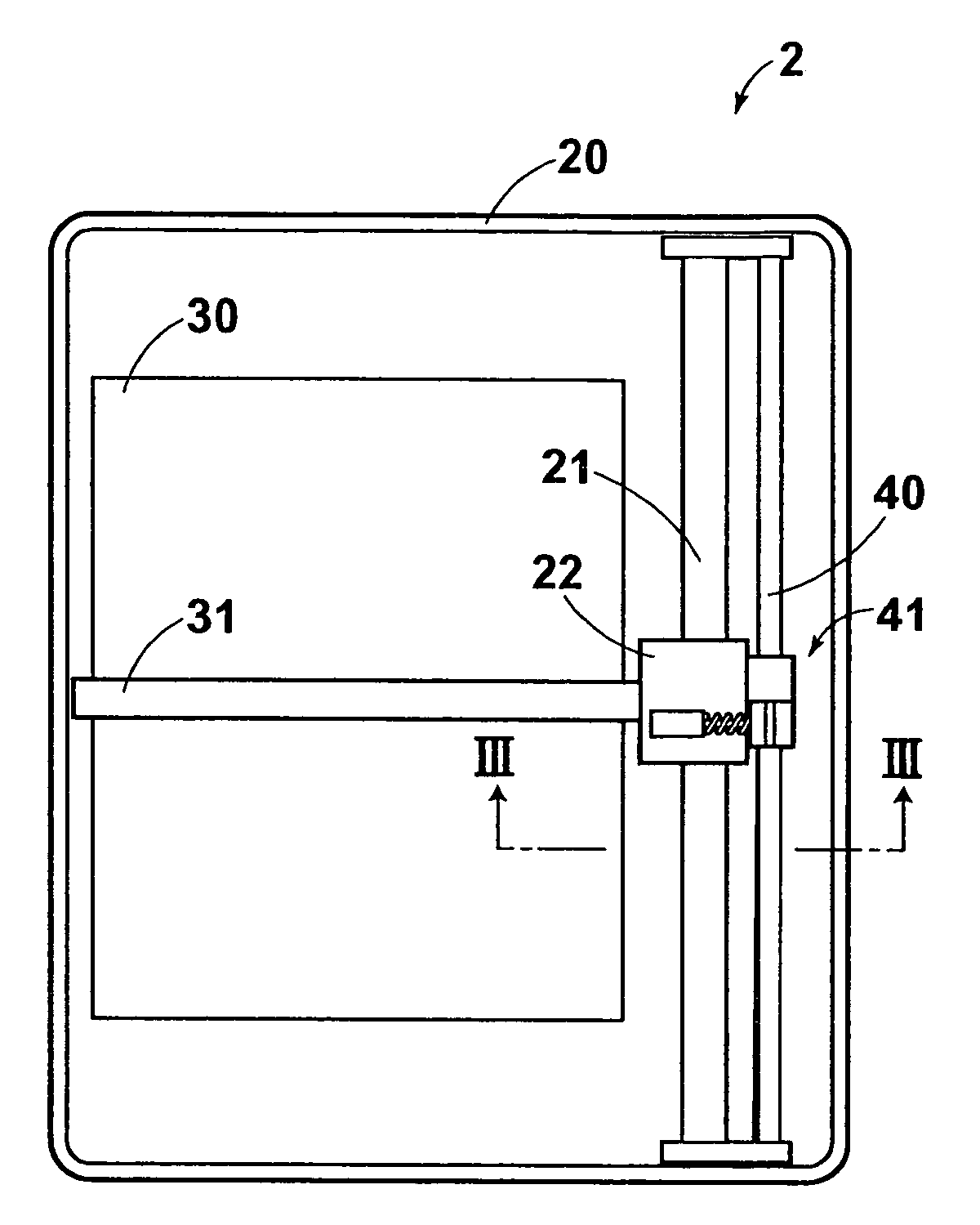
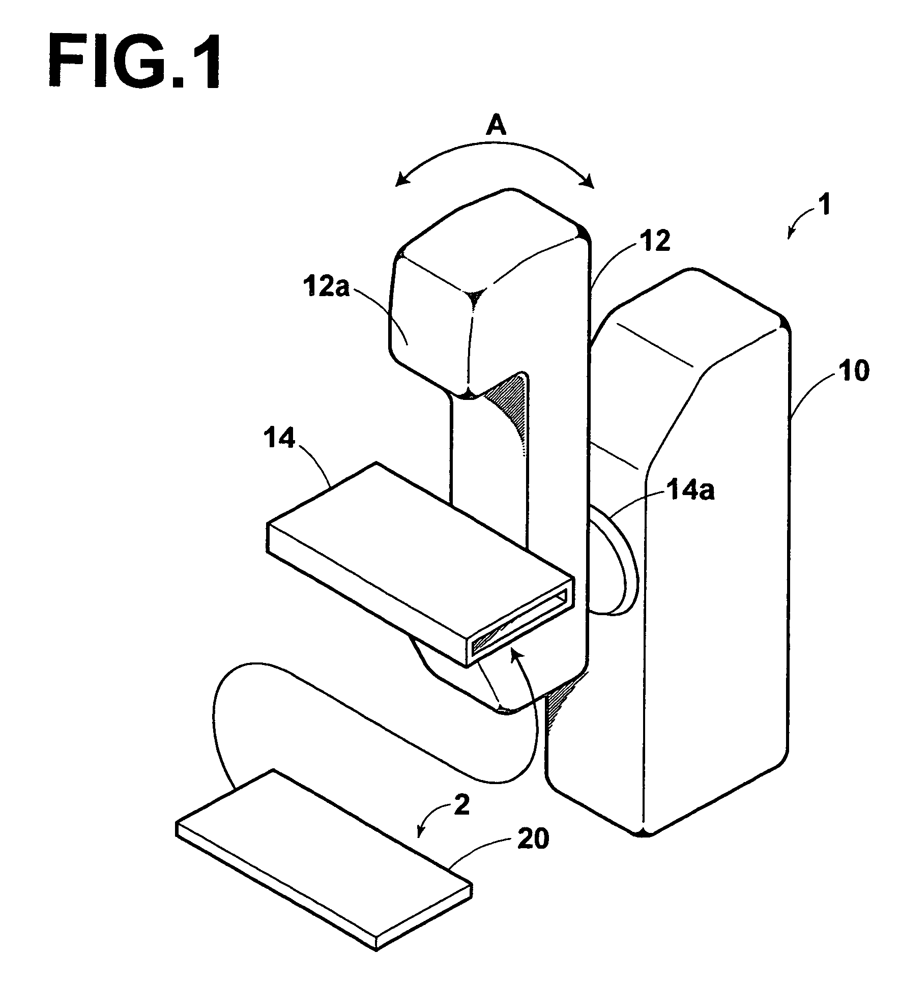
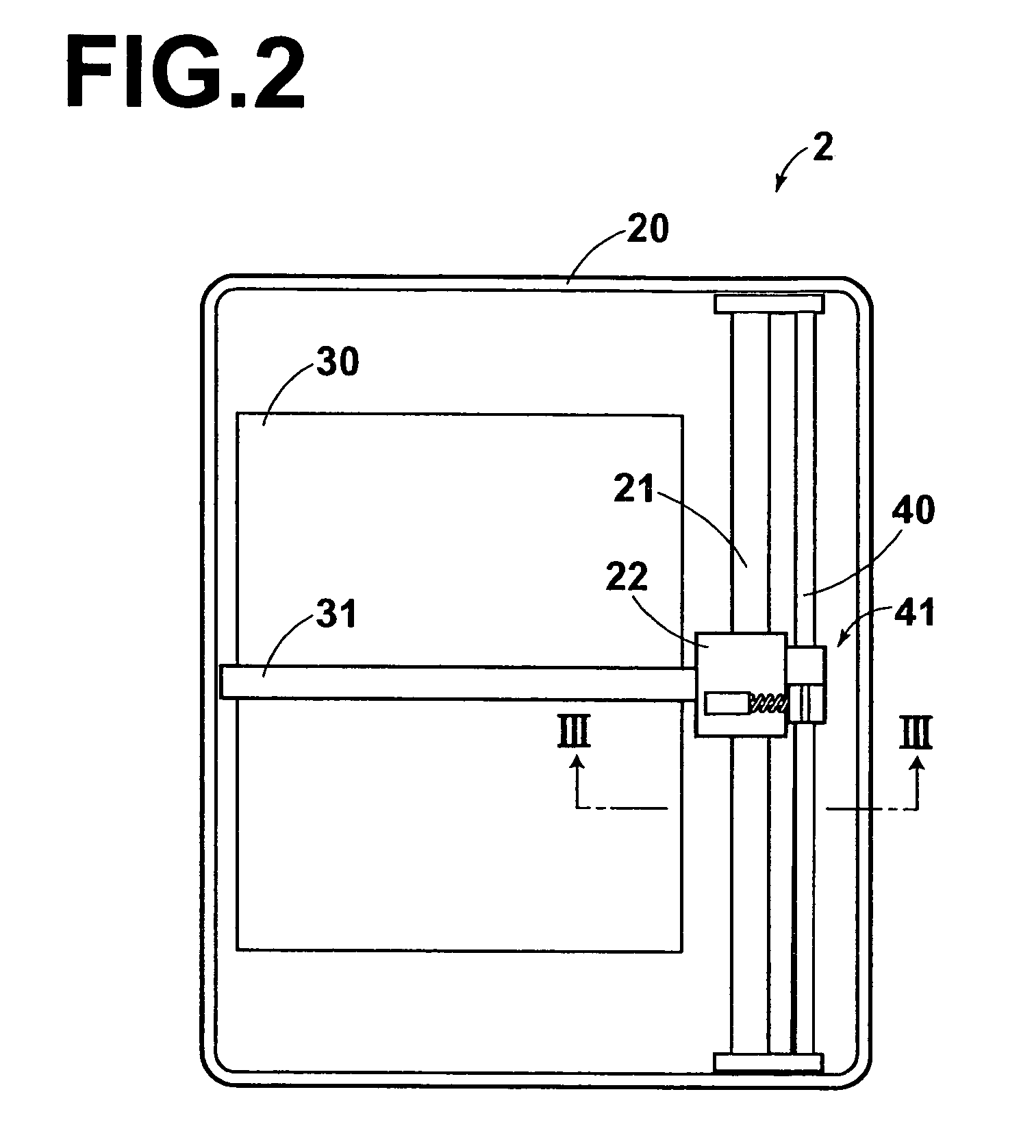
[0021]In FIG. 1, a mammography system employing a scanning system in accordance with a first embodiment of the present invention comprises a system body 1 and a cassette 2 to be loaded in the system body 1.

[0022]The system body 1 comprises an image taking table 10, an arm portion 12 which is provided on the image taking table 10 and a cassette loading portion 14 which is provided on the arm portion 12.

[0023]The arm portion 12 rotates in the direction of arrow A about its junction 14a to the image taking table 10. Further, the arm portion 12 rotates the cassette loading portion 14 in the direction of arrow A. A radiation emitting portion 12a which is part of the arm portion 12 has a radiation source built therein. Radiation emitted from the radiation emitting portion 12a impinges upon the cassette loading portion 14 and a radiation image sensor 30 in the cassette 2 loaded in the cassette loading portion 14. Further, x-raying by the mammography system of this embodiment is carried out...


PUM


Abstract

A scanning system causes a reading light beam to scan a radiation image recording medium which records a radiation image thereon upon exposure to radiation carrying thereon the radiation image and from which a signal is read out according to the radiation image upon exposure to the reading light beam. A mobile body provided with a light source which emits a line-like reading light beam. A driver linearly moves the mobile body in a direction perpendicular to the longitudinal direction of the reading light beam and a holder holds the mobile body in a predetermined position.

Description

BACKGROUND OF THE INVENTION[0001]1. Field of the Invention[0002]This invention relates to a scanning system where a movable body with a light source for projecting reading light is linearly moved to cause the reading light to scan the radiation image recording medium.[0003]2. Description of the Related Art[0004]There have been proposed and put into practice, for instance, in the medical field various radiation image recording media which are irradiated by radiation passing through an object and stores therein a radiation image of the object.[0005]As such a radiation image recording medium, there has been known, for instance, a radiation image sensor using semiconductor material which generates electric charges upon projection of radiation and a stimulable phosphor sheet using stimulable phosphors which store radiation energy upon projection of radiation and emit evanescent light upon projection of reading light.[0006]When a radiation image is read out from such a radiation image rec...

Claims


Application Information

Patent Timeline
Patent Type & Authority Patents(United States)
IPC IPC(8): G03B42/02G06T1/00G21K4/00H01L27/00H04N1/04
CPCG03B42/02
Inventor YAGI, KEIICHI
Owner FUJIFILM HLDG CORP
Learn More