Flexible electrophoretic-type display

a display device and electrophoretic technology, applied in the field of non-missive display devices, can solve the problems of destroying the written image, particle concentration gradients, conventional methods that require the use of relatively costly or hazardous ink types, such as fluorocarbon or solvent-based inks, and achieve the effect of reliable production of high-quality particle-based display devices

Inactive Publication Date: 2008-12-09
PALO ALTO RES CENT INC
View PDF14 Cites 11 Cited by
  • Summary
  • Abstract
  • Description
  • Claims
  • Application Information

AI Technical Summary

Benefits of technology

[0012]The present invention is directed to a particle-based (e.g., electrophoretic or magnetophoretic) display device including an array of microcells containing a particle-based ink having a low specific gravity (e.g., isoparaffinic-based or oil-based) suspension fluid, and sealed with a polymer-based membrane. To overcome the problems of conventional electrophoretic display production methods, the microwell is formed such that a surface of the microwell wall (i.e., either the material forming the wall structure or a surface coating or surface treatment) has a surface energy preferably in the range of 20 to 30 mN / m, and the polymer membrane is formed by overcoating ink-filled microwells with a sealing solution including a polymer suspended in an aqueous or hydroalcoholic solvent. By providing the microwell walls with the desired surface energy, the microwell walls are sufficiently attractive to the isoparaffinic / oil-based suspension fluid that they prevent “floating” of the ink above the aqueous / hydroalcoholic sealing solution. In addition, microwell walls having this surface energy are sufficiently attractive to the aqueous / hydroalcoholic sealing solution such that a reliable connection is established between the polymer and the microwell walls, thereby facilitating the reliable production of high quality particle-based display devices.
[0013]According to another embodiment of the present invention, a method for producing particle-based display devices includes forming an array of microwells, substantially filling the microwells with an ink solution including pigment particles suspended in an isoparaffinic / oil-based suspension fluid, and then overcoating the filled microwells with a sealing solution including a polymer suspended in an aqueous or hydroalcoholic solvent. The use of relatively light ink and relatively heavy sealing solvent is facilitated by forming or coating / treating the microwell walls such that the walls are sufficiently compatible with both the ink and the sealing solution as to both prevent “floating” of the ink, and to promote secure attachment of the polymer membrane formed as the aqueous / hydroalcoholic solvent evaporates from the sealing solution during subsequent curing.

Problems solved by technology

Otherwise the moving liquid would destroy the written image upon bending the display.
Furthermore, paths between the cells tend to cause particle concentration gradients.
A problem with the conventional methods for forming flexible electrophoretic displays is that, by requiring the ink to be relatively heavy (i.e., to have a relatively high specific gravity), the conventional methods require the use of relatively costly or hazardous ink types, such as fluorocarbon or solvent-based inks.
That is, the success of these conventional methods depends strongly on the chemical and physical properties of the ink and the sealing layer compound, and as such require the use of high specific gravity ink solvents that are relatively hazardous, thus increasing the risk of injury during both production and after-sale use.

Method used


Image

  • Flexible electrophoretic-type display
  • Flexible electrophoretic-type display
  • Flexible electrophoretic-type display

Examples


Embodiment Construction

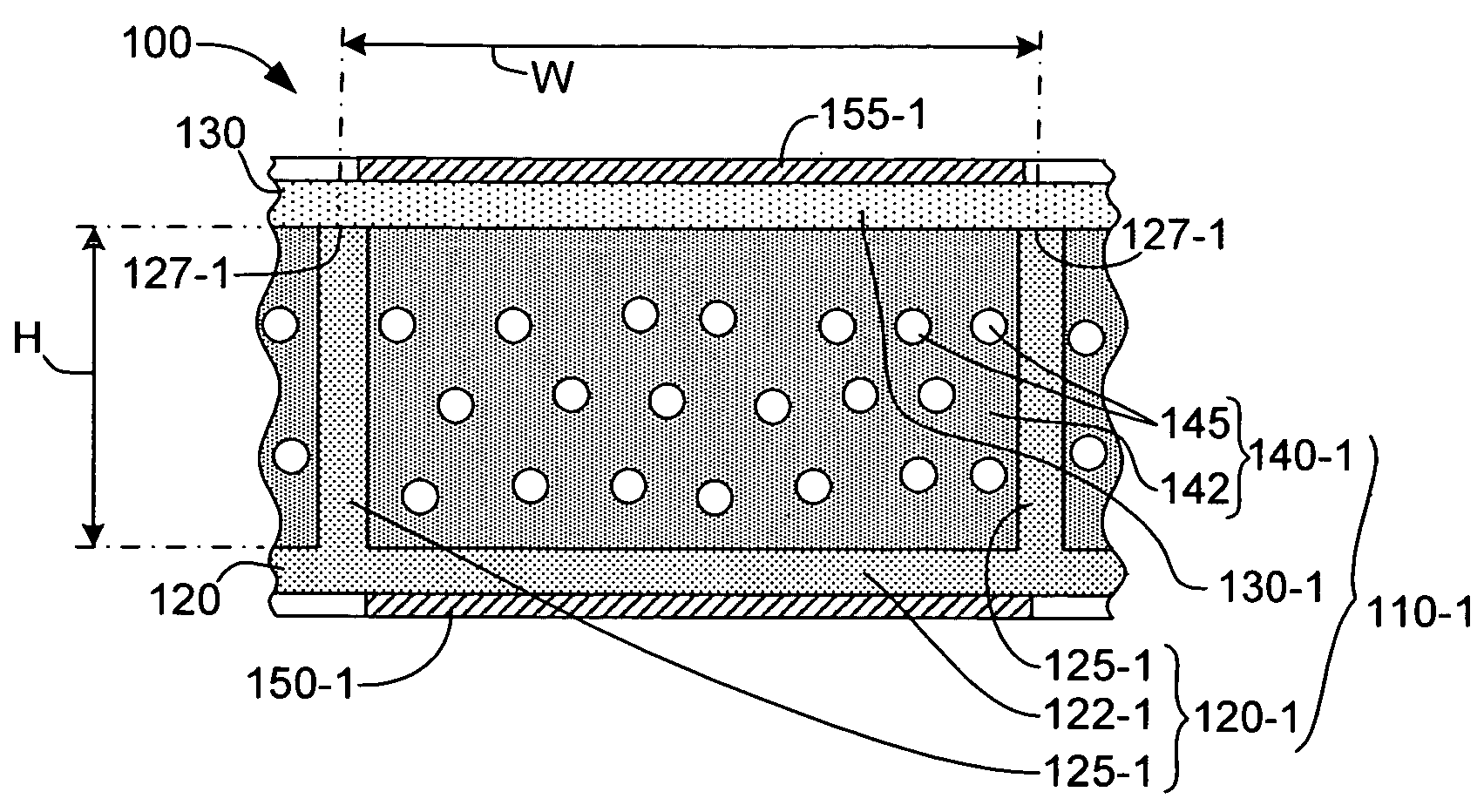
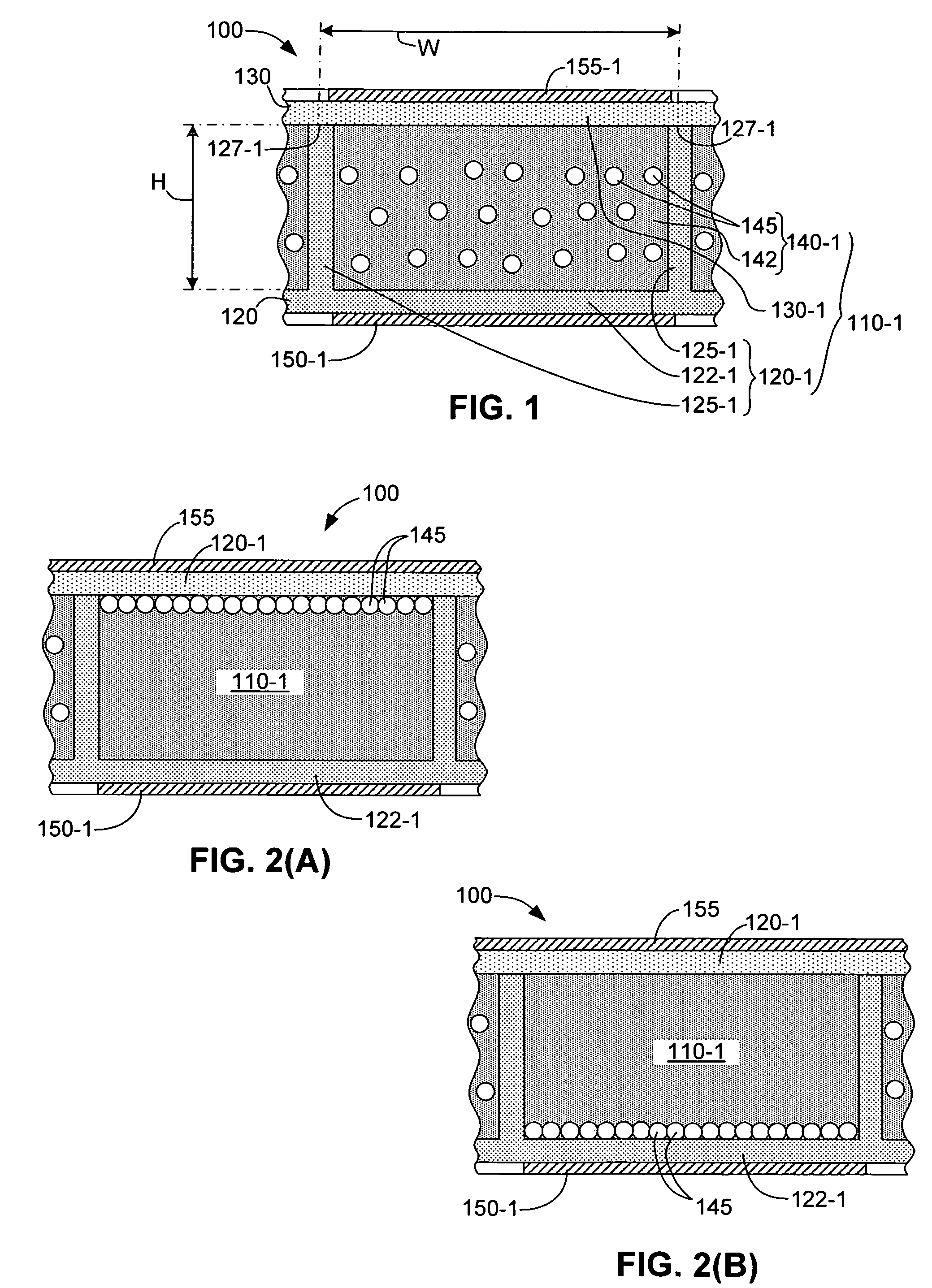
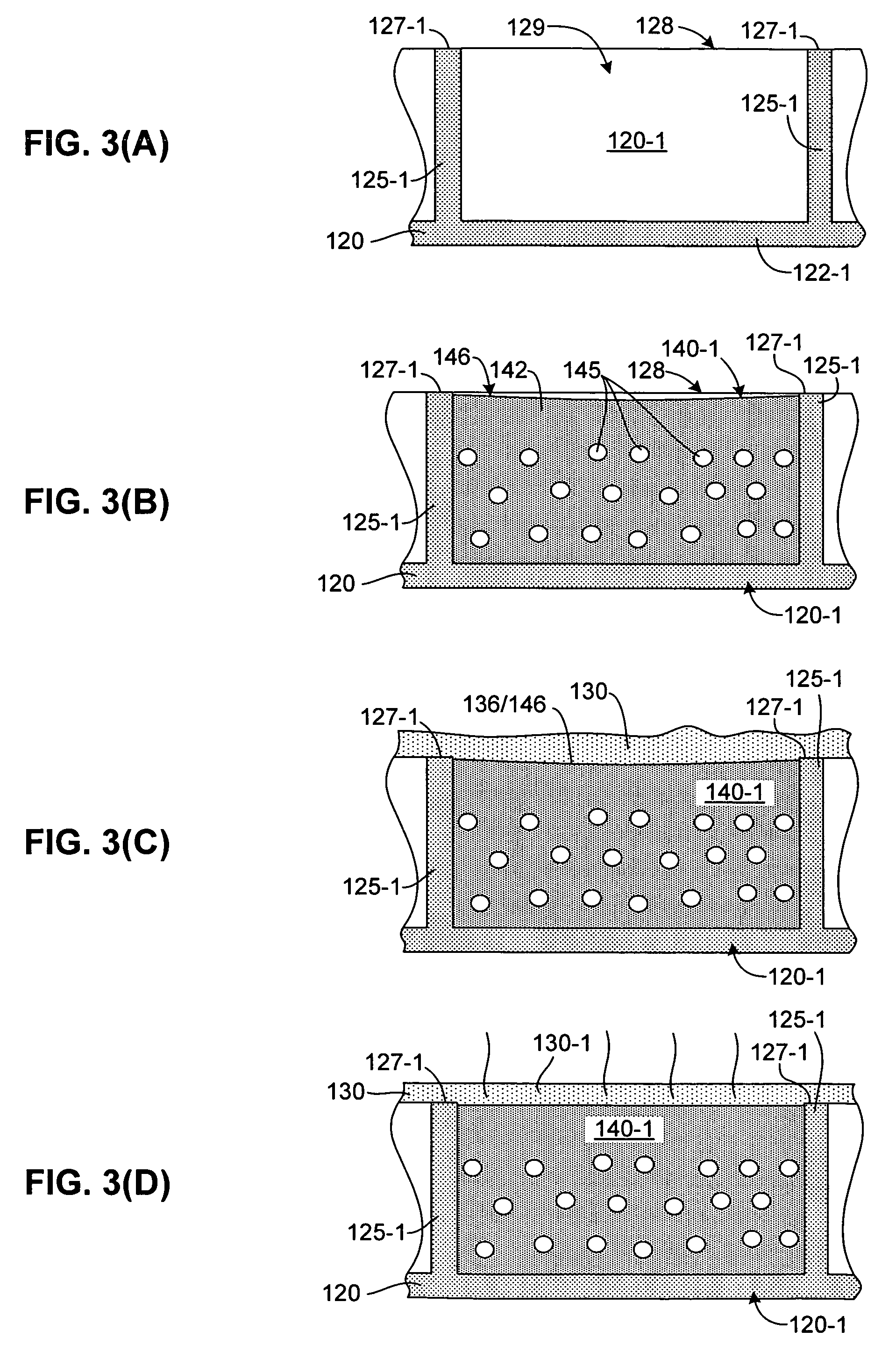
[0023]Unless defined otherwise in this specification, all technical terms are used herein according to their conventional definitions as they are commonly used and understood by those of ordinary skill in the art. The term “microwell” refers to cup-like structures formed in a substantially uniform layer of material by photolithographic patterning, molding, microembossing or other manufacturing process. Each microwell thus includes a lower wall (which may be formed by a substrate on which the microwell material is deposited) and one or more peripheral side walls (e.g., a single circular wall, or three or more contiguous substantially straight walls) that extend upward from the bottom wall and surround a predefined lower wall area, with upper edges of the peripheral side walls defining an open end of the microwell. The term “microcell”-refers to an image unit formed by a sealed microwell (i.e., a microwell including an amount of electrophoretic or other ink and having a sealing membra...


PUM

PropertyMeasurementUnit
surface energyaaaaaaaaaa
heightaaaaaaaaaa
widthaaaaaaaaaa

Abstract

An electrophoretic-type display device including an array of microcells, where each microcell is formed by a microwell containing a quantity of ink and a polymer-based membrane connected to upper edges of the microwell. The membrane is formed by curing an aqueous or hydroalcoholic sealing solution that is overcoated on the ink-filled microwells. The ink includes an isoparaffinic-based or oil-based suspension fluid, and the peripheral side walls of the microwell have a surface energy in the range of 20 to 30 mN / m. The microwell material serves two purposes: to prevent displacement (floating) of the relatively light ink solution above the relatively heavy sealing solution, and to facilitate reliable attachment between the polymer membrane and microwell walls during subsequent curing.

Description

BACKGROUND OF THE INVENTION[0001]1. Field of the Invention[0002]The present invention is directed to non-emissive display devices, and more particularly to flexible particle-based display devices.[0003]2. Related Art[0004]An electrophoretic display represents one type of particle-based, non-emissive display device that includes an array of several thousand independently addressable microcells, each microcell containing a small quantity of electrophoretic ink that is held between a pair of opposed, spaced-apart plate-like electrodes. Each microcell is typically several 10s to 100s of microns in size. The electrophoretic ink includes charged pigment particles suspended in a dyed suspension fluid that is maintained in an enclosed cell region between the electrodes. At least one of the two electrodes is transparent so that the state of the ink can be viewed through the transparent electrode. When a voltage difference is imposed between the two electrodes, the pigment particles migrate t...

Claims


Application Information

Patent Timeline
Patent Type & Authority Patents(United States)
IPC IPC(8): G02B26/00G02F1/133G09G3/34G02F1/167G02F1/1675
CPCG02F1/167G02F1/1675
Inventor DANIEL, JURGENKRUSOR, BRENT S.
Owner PALO ALTO RES CENT INC
Why Eureka
Try Eureka