Electronic system for reducing power supply voltage

Inactive Publication Date: 2008-12-16
HOYA CORP
View PDF10 Cites 6 Cited by
  • Summary
  • Abstract
  • Description
  • Claims
  • Application Information

AI Technical Summary

Benefits of technology

[0008]The present invention is advantageous in that it provides a method and a system capable of protecting a particular circuit of an electronic device by reducing a power supp

Problems solved by technology

However, due to the switching element connected in series with the power supply line supplying electric power to the particular circuit to be protected in case of failure, constant voltage drop is caused by the resistance of the switching element in the normal state (normal operation) of the electronic device.
Further, individual difference

Method used


Image

  • Electronic system for reducing power supply voltage
  • Electronic system for reducing power supply voltage
  • Electronic system for reducing power supply voltage

Examples


Example

[0028]Referring now to the drawings, a description will be given in detail of preferred embodiments in accordance with the present invention.

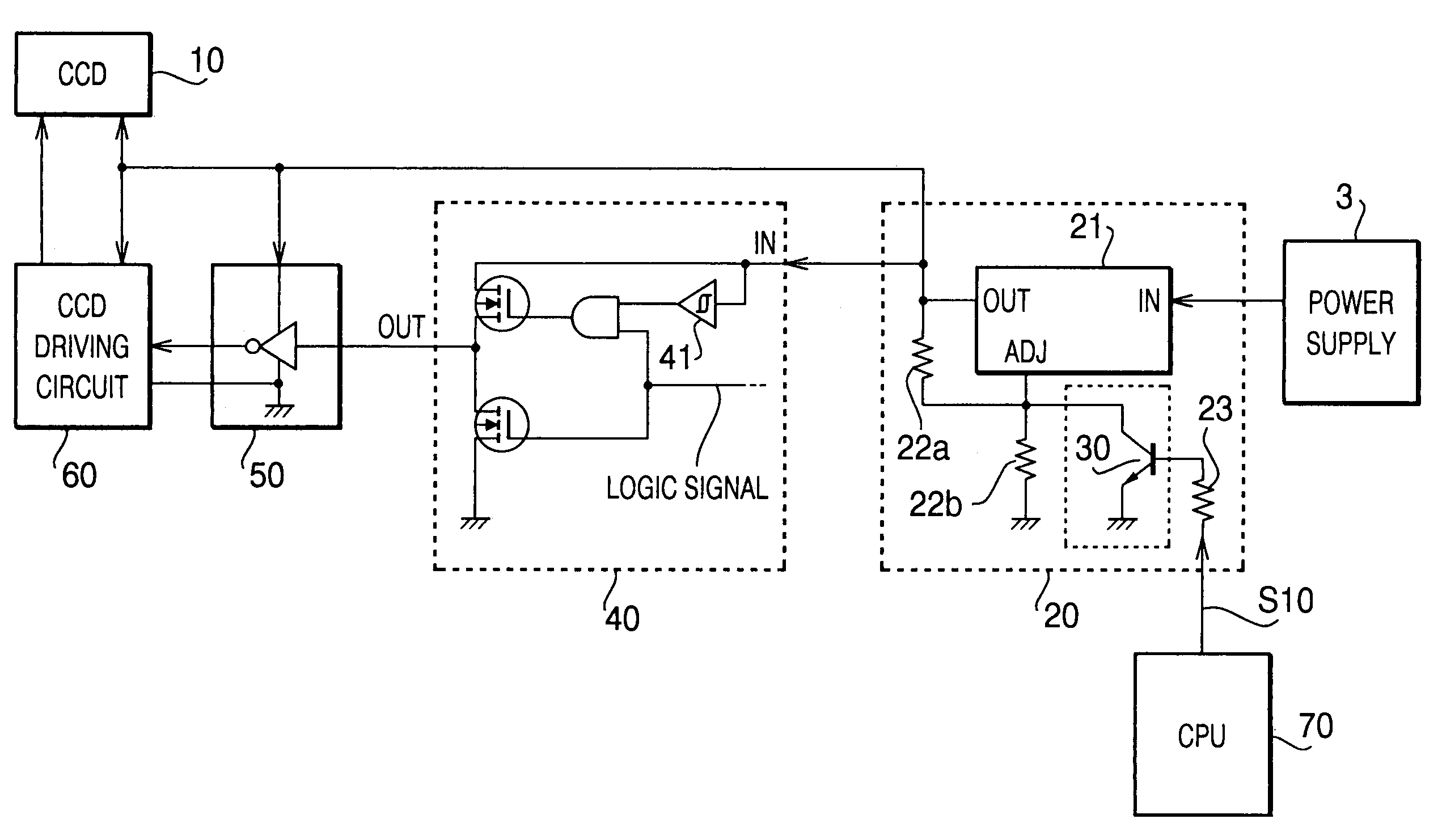
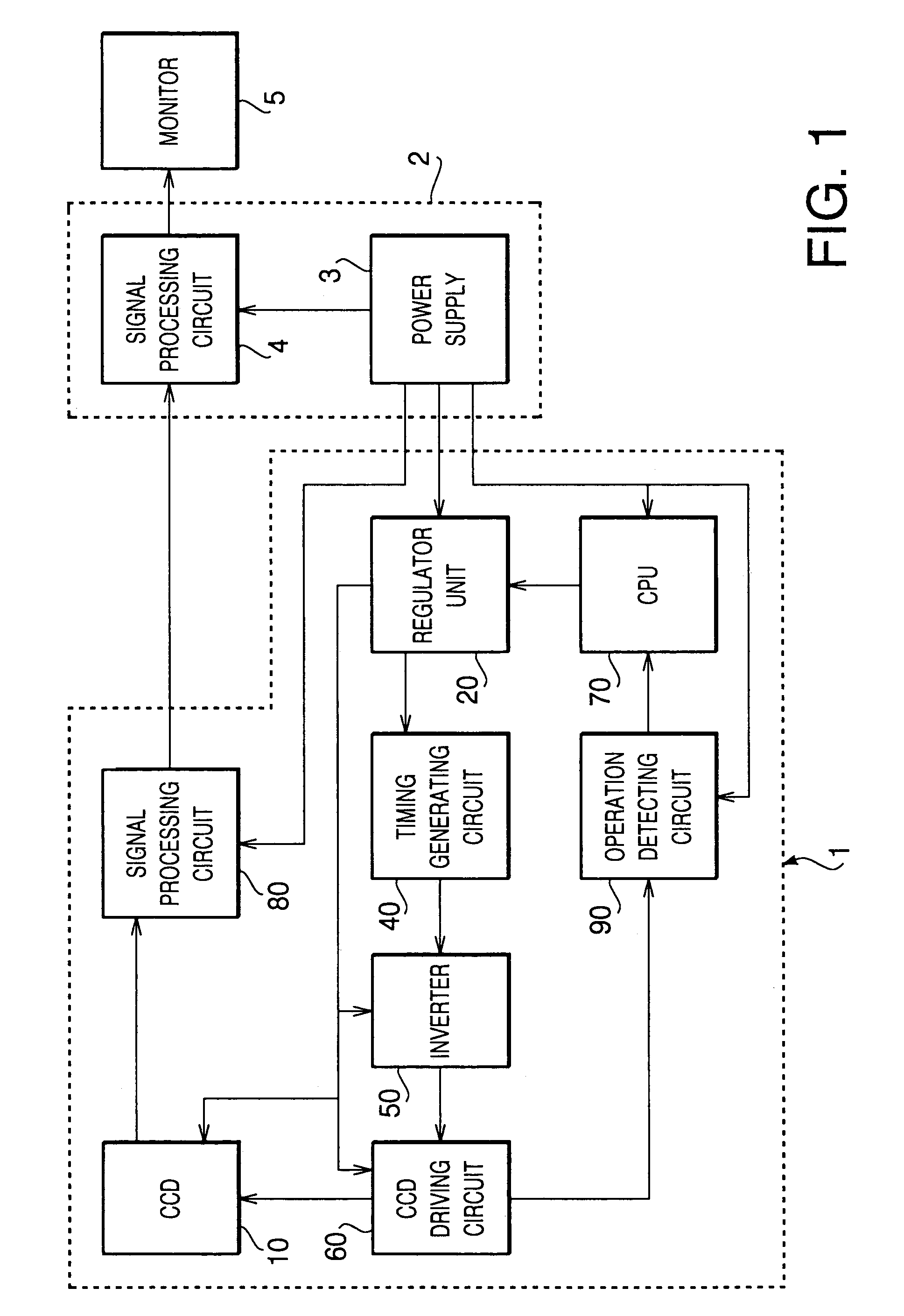
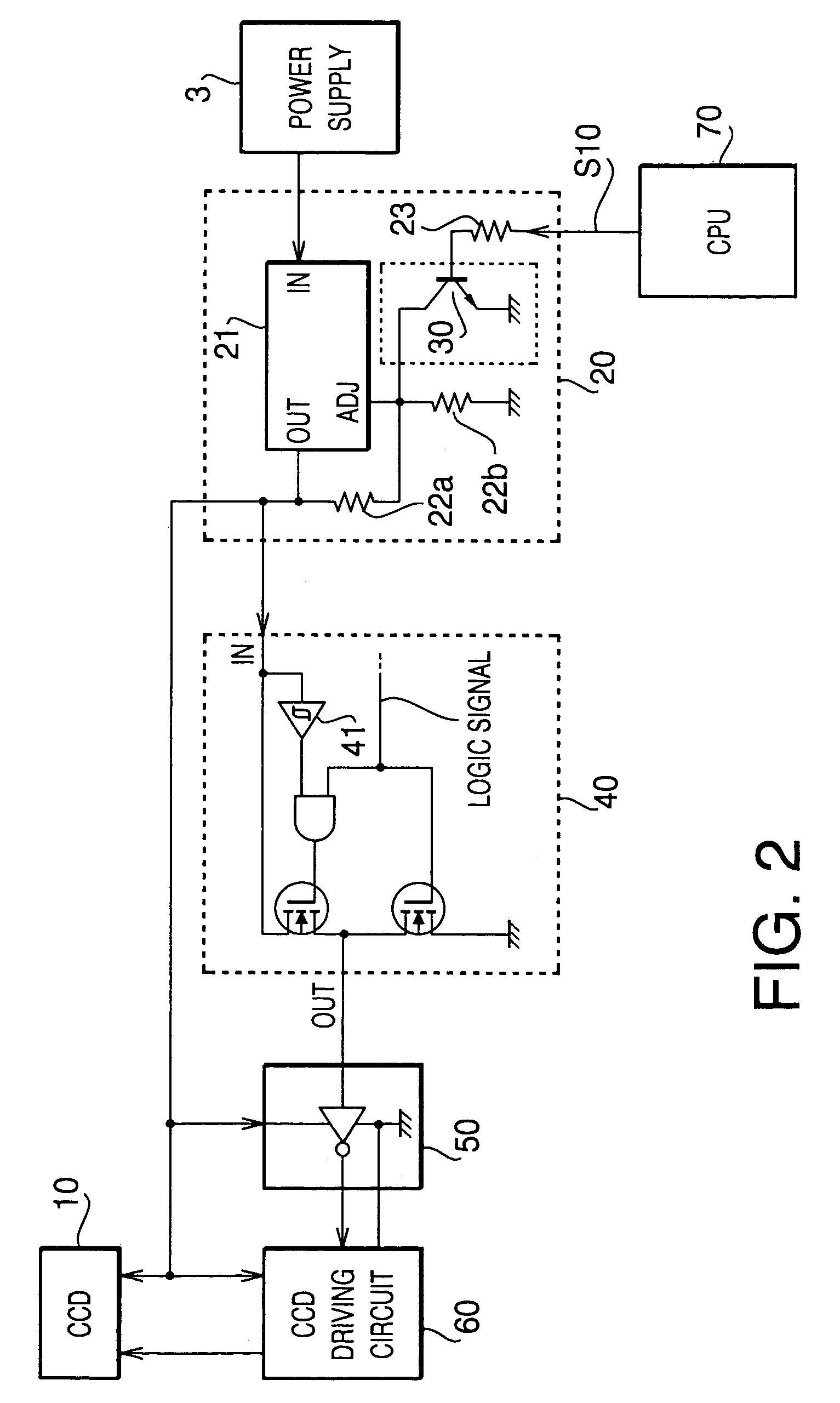
[0029]FIG. 1 is a block diagram showing the composition of an electronic endoscope 1 as an example of an electronic device including a power supply voltage reduction system in accordance with an embodiment of the present invention. The electronic endoscope 1 shown in FIG. 1 includes a regulator unit 20, a timing generating circuit 40, an inverter 50, a CCD 10, a CCD driving circuit 60, a CPU 70, a signal processing circuit 80 and an operation detecting circuit 90. The electronic endoscope 1 is electrically connected to a power supply unit 3 and a signal processing circuit 4 provided in an electronic endoscope processor 2. The signal processing circuit 4 of the processor 2 is connected to a monitor 5.

[0030]The CCD 10 is connected to the CCD driving circuit 60. The CCD driving circuit 60 sends a CCD drive signal to the CCD 10 and thereby control ...


PUM


Abstract

There is provided a method of reducing a power supply voltage which is supplied from a voltage regulator to at least one particular circuit, the voltage regulator being configured to adjust its output voltage by use of an external output voltage setting circuit connected thereto, a switching element being used to connect an output voltage setting terminal of the voltage regulator to a ground via a predetermined resistance. The method includes turning off the switching element so that the output voltage of the voltage regulator is set at a preset power supply voltage for enabling the at least one particular circuit, and turning on the switching element so that the output voltage of the voltage regulator is reduced to a predetermined voltage lower than the preset power supply voltage.

Description

BACKGROUND OF THE INVENTION[0001]The present invention relates to an electronic system and a method for reducing power supply voltage which is supplied by a voltage regulator to an electronic device, in order to protect the electronic device when a certain failure occurs to the electronic device.[0002]Electronic devices such as electronic endoscopes are desired to be equipped with a power supply interruption system for interrupting power supply voltage which is supplied to a particular circuit of the electronic device (e.g., a CCD and a CCD driving circuit of the electronic endoscope) in order to protect the circuit when the certain failure occurred to the electronic device.[0003]FIG. 3 is a circuit diagram showing an example of a conventional power supply interruption system. The power supply interruption system of FIG. 3 controls power supply voltage which is supplied to a CCD circuit, including a timing generator 140, an inverter 150, a CCD driving circuit 160 and a CCD 110, prov...

Claims


Application Information

Patent Timeline
IPC IPC(8): H04N5/335G05F1/56
CPCH04N5/335H04N25/00
Inventor TAKAMI, SATOSHI
Owner HOYA CORP
Why Eureka
Try Eureka