Retain-Till-Accessed Power Saving Mode in High-Performance Static Memories

Active Publication Date: 2011-10-27
TEXAS INSTR INC
View PDF1 Cites 34 Cited by
  • Summary
  • Abstract
  • Description
  • Claims
  • Application Information

AI Technical Summary

Benefits of technology

[0025]Embodiments of this invention can be realized by constructing a static random access memory (SRAM) array constructed of 8-T or 10-T memory cells, for which separate read and write bit lines are provided. A bias device is included in series bet

Problems solved by technology

The power consumption of the electronic circuitry in those devices and systems is therefore of great concern, as battery life is often a significant factor in the buying decision as well as in the utility of the device or system.
However, this physical scaling of device sizes does not necessarily correlate to similar scaling of device electrical characteristics.
However, significant recovery time is typically involved in biasing the memory array to an operational state from the retention state.
Because of its ability to be applied to individual blocks within a larger-scale integrated circuit, as well as its fast recovery time, the RTA standby mode is now often used with embedded memories in modern mobile Internet devices and smartphones, considering that these devices remain powered-on but not fully active for much of their useful life.
As mentioned above, if transistors 13, 14 are extremely small sub-micron devices, these leakage currents can be significant (as much as 1 nA per memory cell), and can thus result in significant overall standby power consumption if the number of memory cells 12 in memory array blocks 6 is large.
However, it is difficult to achieve this optimization because of variations in voltage, temperature, and manufacturing parameters; selection of the size and construction of diodes 8 in the example of FIG. 1a to maximize power savings is thus a difficult proposit

Method used


Image

  • Retain-Till-Accessed Power Saving Mode in High-Performance Static Memories
  • Retain-Till-Accessed Power Saving Mode in High-Performance Static Memories
  • Retain-Till-Accessed Power Saving Mode in High-Performance Static Memories

Examples


Example

[0034]The present invention will be described in connection with its preferred embodiment, namely as implemented into an integrated circuit including an embedded memory array, and constructed according to complementary metal-oxide-semiconductor (CMOS) technology. However, it is contemplated that the benefits of this invention may be attained when realized in other applications and constructed according to other technologies. Accordingly, it is to be understood that the following description is provided by way of example only, and is not intended to limit the true scope of this invention as claimed.

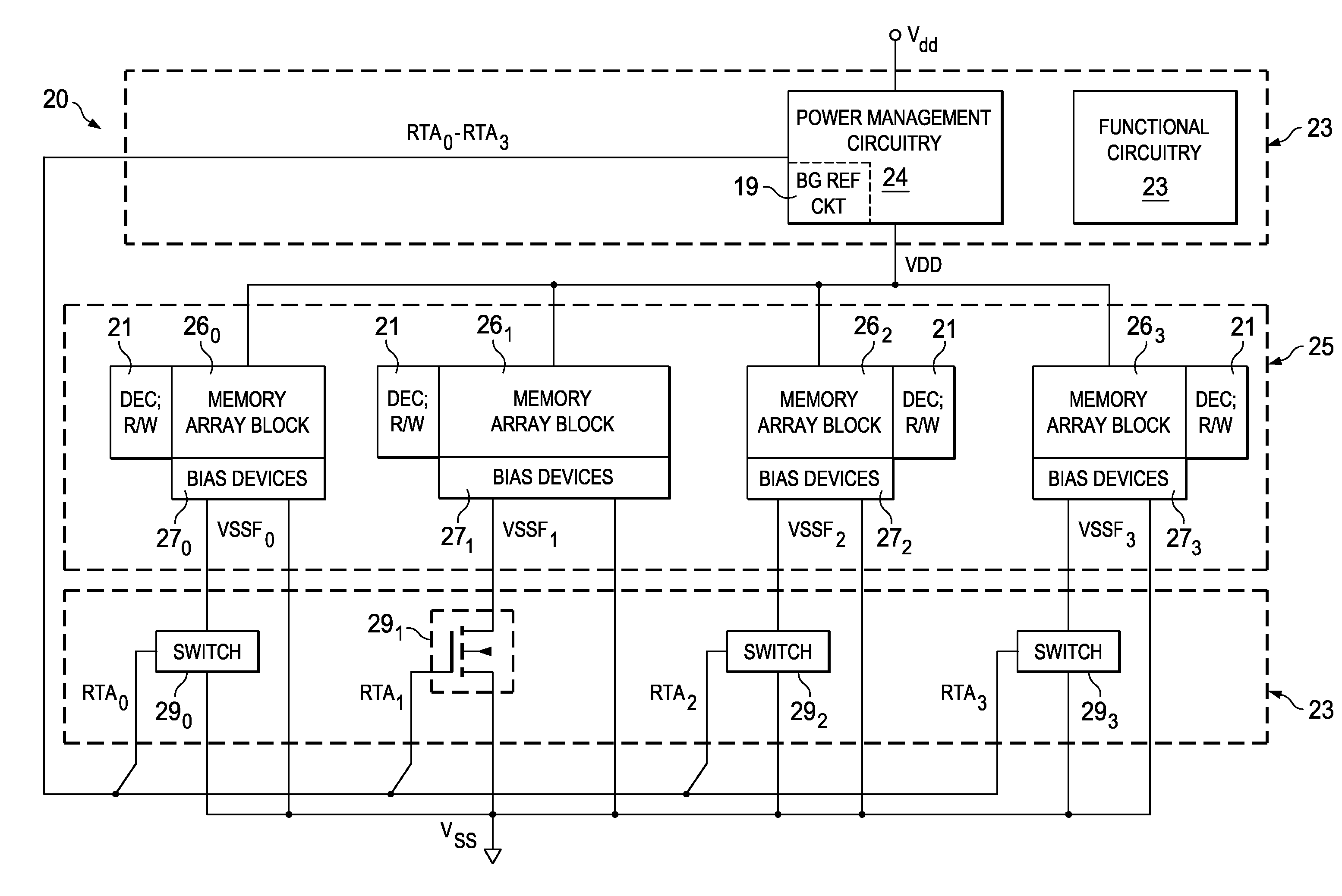
[0035]Referring now to FIG. 2, by way of example, integrated circuit 20 constructed according to embodiments of this invention will now be described at a block diagram level. As shown in FIG. 2, integrated circuit 20 includes functional circuitry 23, power management circuitry 24, and memory array 25. The functionality provided by functional circuitry 23 may vary widely depending on the de...


PUM


Abstract

Bias circuitry for a static random-access memory (SRAM) with a retain-till-accessed (RTA) mode. The memory is constructed of multiple memory array blocks, each including SRAM cells of the 8-T or 10-T type, with separate read and write data paths. Bias devices are included within each memory array block, for example associated with individual columns, and connected between a reference voltage node for cross-coupled inverters in each memory cell in the associated column or columns, and a ground node. In a normal operating mode, a switch transistor connected in parallel with the bias devices is turned on, so that the ground voltage biases the cross-coupled inverters in each cell. In the RTA mode, the switch transistors are turned off, allowing the bias devices to raise the reference bias to the cross-coupled inverters, reducing power consumed by the cells in that mode.

Description

CROSS-REFERENCE TO RELATED APPLICATIONS[0001]This application is related to commonly assigned U.S. patent applications Ser. No. 12 / ______, entitled “Reduced Power Consumption in Retain-Till-Accessed Static Memories”, and Ser. No. 12 / ______, entitled “Combined Write Assist and Retain-Till-Accessed Memory Array Bias”, both filed contemporaneously herewith and incorporated herein by reference.STATEMENT REGARDING FEDERALLY SPONSORED RESEARCH OR DEVELOPMENT[0002]Not applicable.BACKGROUND OF THE INVENTION[0003]This invention is in the field of integrated circuits. Embodiments of this invention are more specifically directed to solid-state static random access memories (SRAMs), and power reduction in those SRAMs.[0004]Many modern electronic devices and systems now include substantial computational capability for controlling and managing a wide range of functions and useful applications. Many of these electronic devices and systems are now handheld portable devices. For example, many mobile...

Claims


Application Information

Patent Timeline
IPC IPC(8): G11C11/40G11C5/14
CPCG11C11/417
Inventor SESHADRI, ANAND
Owner TEXAS INSTR INC
Why Eureka
Try Eureka