Objective optical system for an endoscope

an endoscope and optical system technology, applied in the field of high image quality objective optical systems for endoscopes, can solve the problems of insufficient depth of field that must be compensated, long moving lens group with a frame, and difficult to obtain a proper balance of optical specifications with pan focus

Active Publication Date: 2008-12-16
OLYMPUS CORP
View PDF14 Cites 61 Cited by
  • Summary
  • Abstract
  • Description
  • Claims
  • Application Information

AI Technical Summary

Problems solved by technology

However, it becomes difficult to obtain a proper balance of optical specifications with pan focus due to effects of lowering sensitivity caused by the reduction of pixels with solid-state image pickup elements and deterioration of contrast caused by diffraction and other factors.
Additionally, optical specifications when adopting progressive read-out type, primary color, single-plate image pickup units or multi-plate image pickup units, such as two-plate or three-plate units, which provide a high precision image other than by increasing the number of pixels, are not established with pan focusing.
Therefore, in an objective optical system that provides high precision images, a decrease of f-number that is necessary to ensure a sufficient image brightness for viewing a high precision image results in an insufficient depth of field that must be compensated for by including a focusing function in the objective optical system.
It is unavoidable that a moving lens group with a frame becomes long and heavy when the moving group is composed of plural lens components.
This is undesirable because the torque of an actuator for moving the moving lens group increases and the actuator becomes large in size.
Additionally, these optical systems are undesirable as optical systems for endoscopes strictly in terms of focusing considerations because the fluctuations of focal length associated with the lens movement are too large.
In embodiments of objective lenses for endoscopes described in the above cited Japanese Laid-Open Patent Application 2000-330015 and embodiments of an endoscope device described in the above cited Japanese Laid-Open Patent Application 2002-28126, the moving lens component is on the image most side, and these embodiments are undesirable because of the large outside diameter of the lenses required, and the large size in the radial direction of any frame mounting such a large size lens that is used with any mechanism for moving such a lens.
This optical system is undesirable for use in combination with primary color single plate image pickup elements or multiplate image pickup units, such as two-plate or three-plate units, because the exit pupil distance is generally shortened.

Method used


Image

  • Objective optical system for an endoscope
  • Objective optical system for an endoscope
  • Objective optical system for an endoscope

Examples


embodiment 1

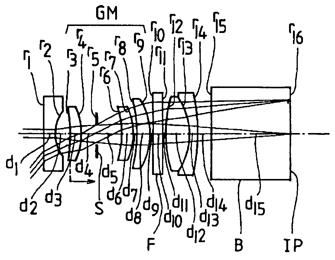
[0134]FIG. 1 shows a cross-sectional view of the objective optical system for an endoscope of Embodiment 1 of the present invention. In FIG. 1, as well as in FIGS. 2-26, IP is the image plane. Table 1 below lists the various data explained above for Embodiment 1.

[0135]

TABLE 1Far point focused stateWD = 48fTF = 1.790FNO = 4.482 ω = 98.6°Near point focused stateWD = 23fTN = 1.758FNO = 4.482 ω = 100.9°r1 = ∞d1 = 0.5000n1 = 1.76820ν1 = 71.79r2 = 1.4291d2 = 0.6995r3 = −6.9299d3 = 0.5800n2 = 1.72916ν2 = 54.68r4 = −2.5937d4 = 0.6725r5 = ∞ (stop)d5 = 1.0825r6 = −4.1260d6 = 0.6000n3 = 1.72916ν3 = 54.68r7 = −2.6280d7 = 0.1000r8 = −6.3523d8 = 0.6000n4 = 1.80610ν4 = 40.92r9 = −3.0721d9 = 0.1000r10 = ∞d10 = 0.4500n5 = 1.51800ν5 = 75.00r11 = ∞d11 = 0.1000r12 = 5.1077d12 = 1.1000n6 = 1.58913ν6 = 61.14r13 = −2.7000d13 = 0.3000n7 = 1.92286ν7 = 18.90r14 = −8.6620d14 = 0.6000r15 = ∞d15 = 3.6000n8 = 1.48749ν8 = 70.23r16 = ∞ (image plane)|fUM / fTF| = 3.006fU1 / fTF = −1.039fTN / fTF = 0.982fU1 = −1.860fU1 / fT...

embodiment 2

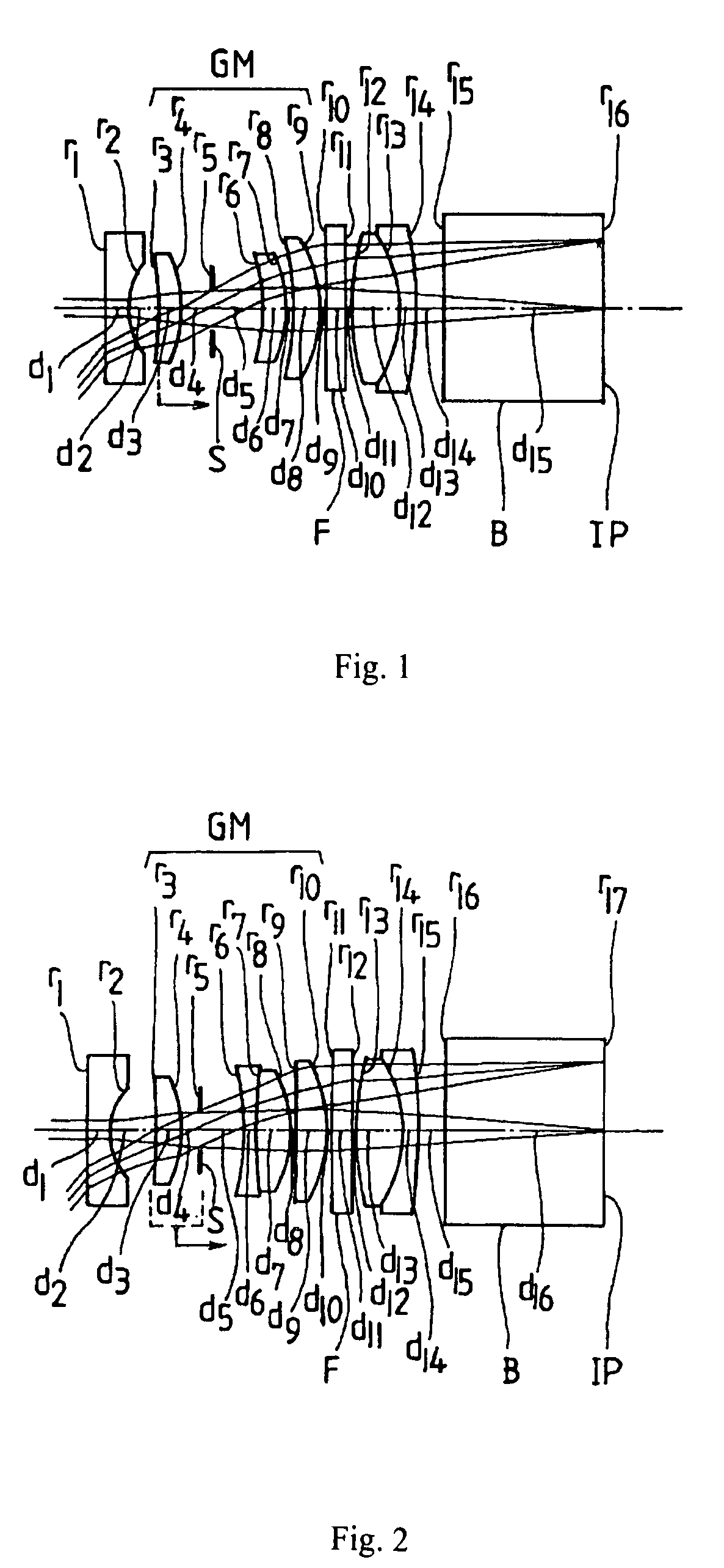
[0141]FIG. 2 shows a cross-sectional view of the objective optical system for an endoscope of Embodiment 2 of the present invention. Table 2 below lists the various data explained above for Embodiment 2.

[0142]

TABLE 2Far point focused stateWD = 47fTF = 1.800FNO = 4.522 ω = 98.6°Near point focused stateWD = 23fTN = 1.765FNO = 4.552 ω = 100.9°r1 = ∞d1 = 0.5000n1 = 1.76820ν1 = 71.79r2 = 1.4200d2 = 1.0546r3 = −11.8050d3 = 0.6000n2 = 1.80100ν2 = 34.97r4 = −2.8044d4 = 0.3904r5 = ∞ (stop)d5 = 1.0008r6 = −5.1964d6 = 0.3000n3 = 1.80518ν3 = 25.42r7 = 16.3100d7 = 0.7500n4 = 1.51742ν4 = 52.43r8 = −2.7213d8 = 0.1000r9 = −30.4133d9 = 0.6500n5 = 1.83481ν5 = 42.71r10 = −3.6000d10 = 0.1000r11 = ∞d11 = 0.4500n6 = 1.51800ν6 = 75.00r12 = ∞d12 = 0.1000r13 = 6.2138d13 = 1.0000n7 = 1.58913ν7 = 61.14r14 = −2.8000d14 = 0.3000n8 = 1.84666ν8 = 23.78r15 = −17.3297d15 = 0.6000r16 = ∞d16 = 3.6000n9 = 1.48749ν9 = 70.23r17 = ∞ (image plane)|fUM / fTF| = 2.478fU1 / fTF = −1.027fTN / fTF = 0.981fU1 = −1.848fU1 / fTF = −1.03f...

embodiment 3

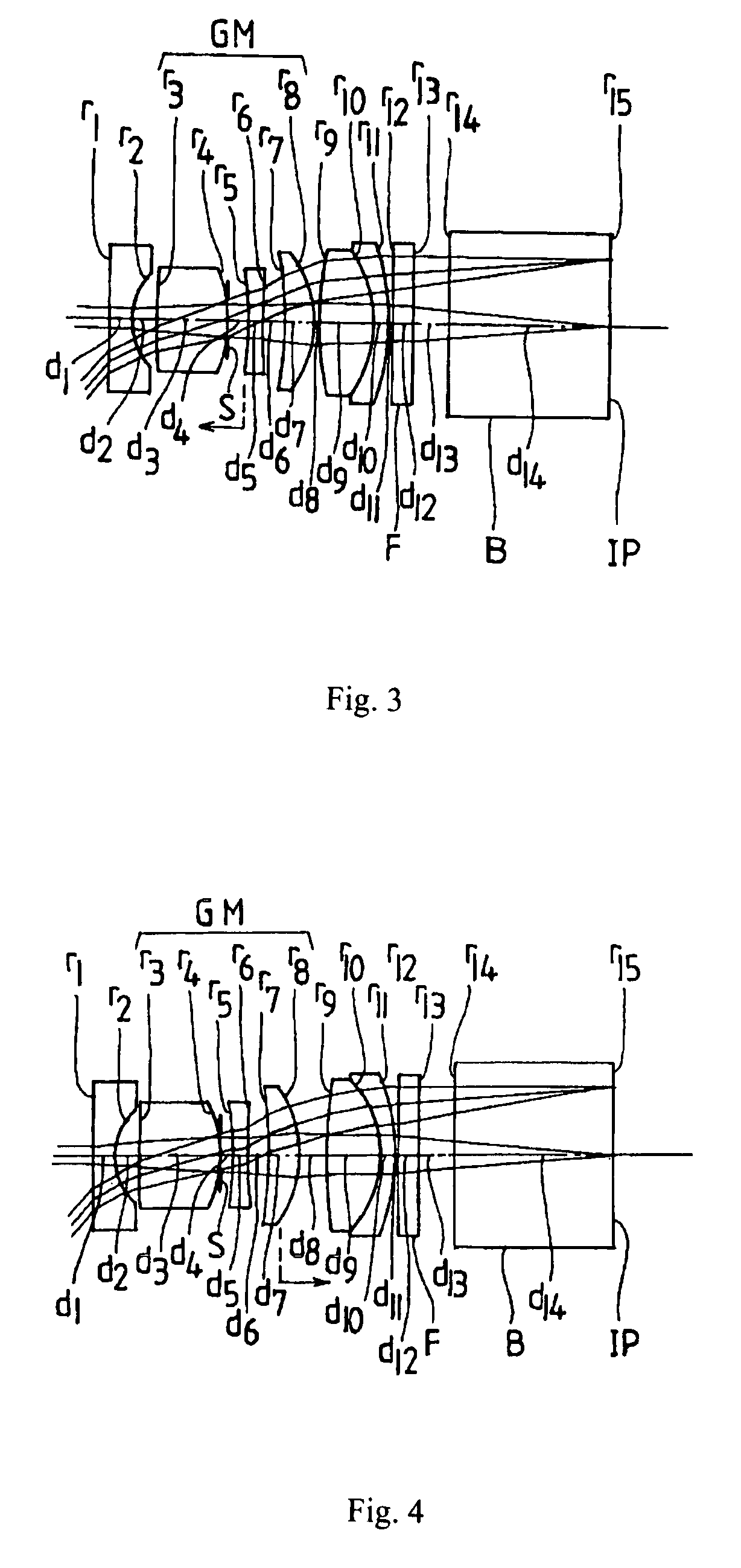
[0150]FIG. 3 shows a cross-sectional view of the objective optical system for an endoscope of Embodiment 3 of the present invention. Table 3 below lists the various data explained above for Embodiment 3.

[0151]

TABLE 3Far point focused stateWD = 46fTF = 1.845FNO = 4.462 ω = 98.6°Near point focused stateWD = 23fTN = 1.789FNO = 4.352 ω = 102.6°r1 = ∞d1 = 0.5000n1 = 1.76820ν1 = 71.79r2 = 1.3633d2 = 0.5500r3 = 9.9958d3 = 1.6230n2 = 1.80100ν2 = 34.97r4 = −3.4155 (stop)d4 = 0.5076r5 = −6.3158d5 = 0.3000n3 = 1.88300ν3 = 40.76r6 = 13.0944d6 = 0.5000r7 = −8.2243d7 = 0.7000n4 = 1.72916ν4 = 54.68r8 = −2.2479d8 = 0.1000r9 = 6.1134d9 = 1.2000n5 = 1.72916ν5 = 54.68r10 = −2.7228d10 = 0.3000n6 = 1.92286ν6 = 18.90r11 = −6.2637d11 = 0.1000r12 = ∞d12 = 0.4500n7 = 1.51800ν7 = 75.00r13 = ∞d13 = 0.8000r14 = ∞d14 = 3.6000n8 = 1.48749ν8 = 70.23r15 = ∞ (image plane)|fUM / fTF| = 2.597fU1 / fTF = −0.962fTN / fTF = 0.970fU1 = −1.775fU1 / fTF = −0.96fU2 = 3.359fU2 / fTF = 1.82fU3 = −4.791fU3 / fTF = −2.60fU4 = 4.043fU4 / fTF ...


PUM


Abstract

An objective optical system is disclosed that is suitable for a high-precision endoscope that performs focusing by moving a single lens component. The objective optical system includes, in order from the object side, a front lens group, a middle lens group, and a rear lens group. The middle lens group is composed of two or more lens components, at least two of which have positive refractive power, and the lens component that is moved for focusing is in the middle lens group. Additionally, the objective optical system satisfies two specified conditions, and other conditions may apply.

Description

[0001]This application claims benefit of foreign priority under 35 U.S.C. 119 of Japanese Patent Application No. 2006-287437 filed on Oct. 23, 2006, the contents of which are hereby incorporated by reference.TECHNICAL FIELD OF THE INVENTION[0002]The present invention relates to a high image quality objective optical system for an endoscope.BACKGROUND OF THE INVENTION[0003]In a so-called videoscope mounted with solid-state image pickup elements at the tip of the insertion portion of an endoscope, a system for outputting a high precision video signal of HDTV specification and / or PC format has been commercialized. It is easy to realize a videoscope of standard specifications with pan focus if it has NTSC / PAL resolution. However, it becomes difficult to obtain a proper balance of optical specifications with pan focus due to effects of lowering sensitivity caused by the reduction of pixels with solid-state image pickup elements and deterioration of contrast caused by diffraction and othe...

Claims


Application Information

Patent Timeline
Patent Type & Authority Patents(United States)
IPC IPC(8): G02B3/00
CPCG02B23/2438A61B1/00188
Inventor IGARASHI, TSUTOMU
Owner OLYMPUS CORP
Why Eureka
Try Eureka