Conversion correcting method of color image data and photographic processing apparatus implementing the method

a technology of conversion correction and color image data, which is applied in the direction of digitally marking record carriers, color signal processing circuits, instruments, etc., can solve the problems of affecting the color reproducibility of the output image data of the respective color components, and affecting the color reproducibility of the correction. , to achieve the effect of preventing loss or disturbance of the original color balance and reducing the disadvantage of color reproducibility

Inactive Publication Date: 2008-12-16
NORITZ CORP
View PDF13 Cites 5 Cited by
  • Summary
  • Abstract
  • Description
  • Claims
  • Application Information

AI Technical Summary

Benefits of technology

[0022]In view of the above-described state of the art, one object of the present invention is to provide an image processing technique capable of preventing loss or disturbance in the original color balance in output image data to be obtained after input/output conversions of color image data using a mathematical correction function shifted in a coord

Problems solved by technology

In this, in the conversion of the input image data into the output image data by suing the above-described correction function, if the chopping is effected for digital image data of at least one color component, the chopping may result in disturbance or loss of the original color balance among the output image data of the resp

Method used


Image

  • Conversion correcting method of color image data and photographic processing apparatus implementing the method
  • Conversion correcting method of color image data and photographic processing apparatus implementing the method
  • Conversion correcting method of color image data and photographic processing apparatus implementing the method

Examples


first embodiment

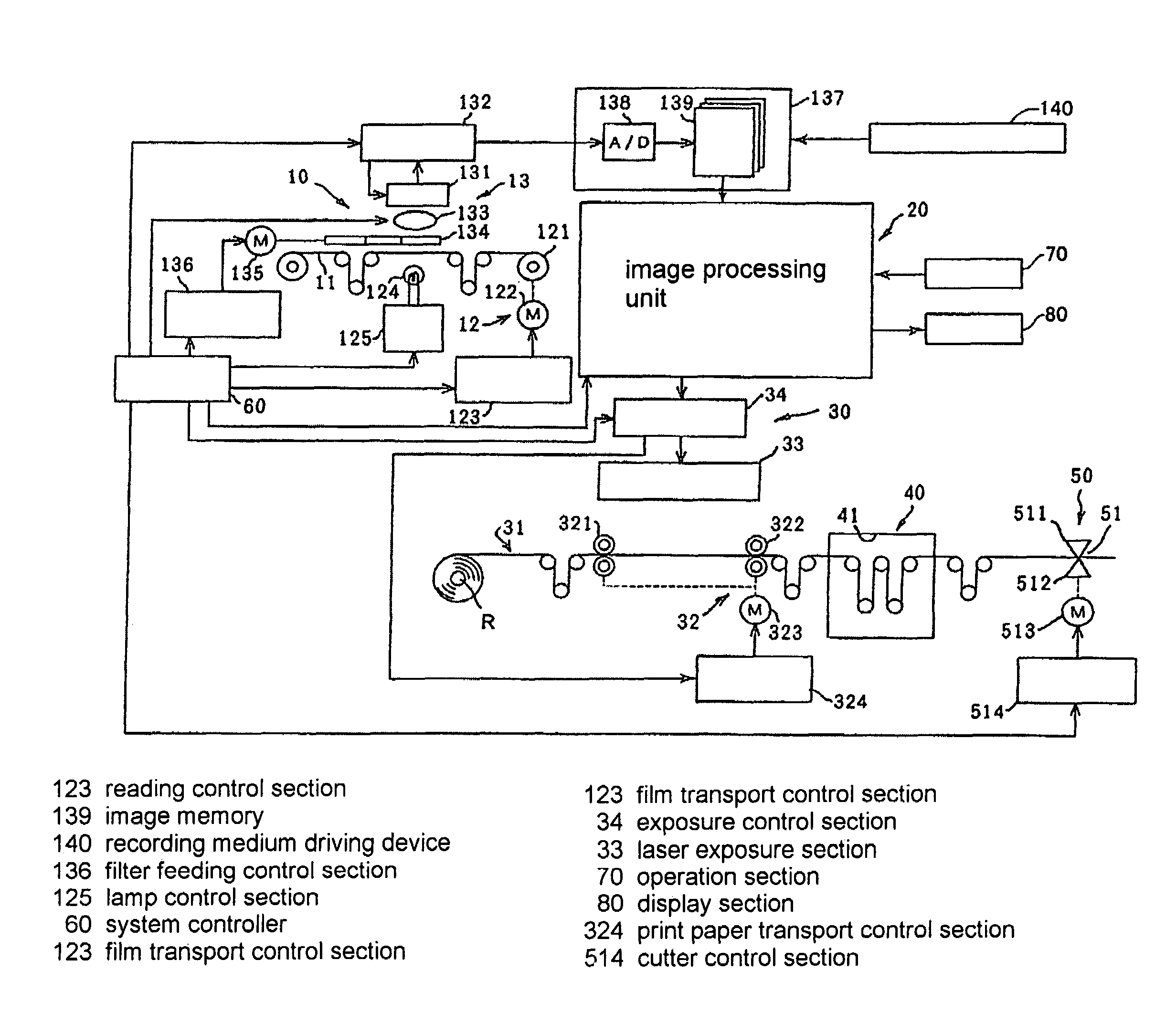
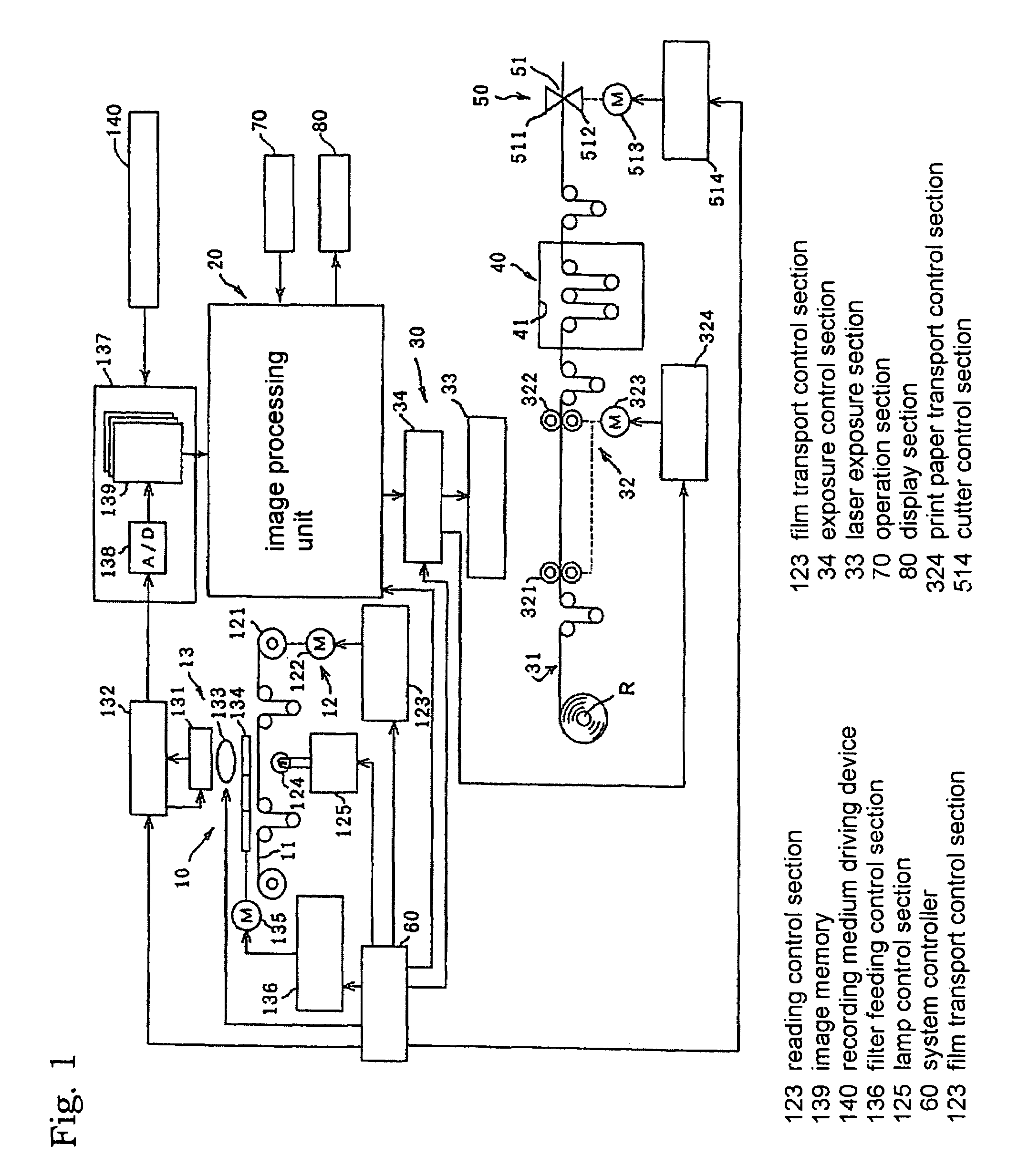
[0064]FIG. 1 is a view showing a schematic construction of a photographic processing apparatus implementing an image processing technique relating to the present invention. In this figure, the photographic processing apparatus includes a film scanner 10 for reading an image from e.g. a developed negative film or positive film and storing the image therein, an image processing unit 20 for effecting a predetermined image processing on image data sent from the film scanner 10 or image data directly read from an image recording medium, an image exposure section 30 for converting the processed image data into optical signals and exposing a print paper, a development section 40 for developing the exposed print paper, a cutting section 50 for cutting the developed and dried print paper into a one-frame piece, and a system controller 60 for controlling the operations of the entire system.

[0065]The film scanner 10 includes a film transporting section 12 for transporting the each frame of the...

example 1

[0098]For a pixel A having input gradation values of IN (B, G, R)=(150, 200, 250), suppose correction values: (b, g, r)=(200, 250, 300) were obtained from the correction function. In this, since the density correction section 23 outputs 8-bit digital image data, the maximum output gradation value is 255. Therefore, the correction value: r=300 obtained from the correction function overflows from the possible range of the output gradation. Therefore, this pixel A is judged as an inappropriate pixel by the judging section 21a. Hence, the chopping is effected on this: r=300 of the pixel A, thereby to obtain: (B, G, R)=(200, 250, 255).

[0099]Next, for the pixel A, the calculating section 21b calculates the differences Δb, Δg, Δr and DR. Of the correction values b, g, r obtained from the correction function, the minimum value is b=200 and the maximum value is r=300. Then, the above calculations are carried out as:

Δb=b−min=200−200=0

Δg=g−min=250−200=0.50

Δr=r−min=300−200=100

DR=max−min=300−200...

example 2

[0104]For a pixel C having input gradation values of IN (B, G, R)=(0, 50, 100), suppose correction values: (b, g, r)=(−50, 0, 100) were obtained from the correction function in the density correction. In this, the minimum output gradation value of the digital image data outputted from the density correction section 23 is 0. Therefore, the correction value: b=−50 obtained from the correction function underflows from the possible range of the output gradation. Therefore, this pixel C is judged as an inappropriate pixel by the density correction section 23. Hence, the chopping is effected on this: b=−50 of the pixel C, thereby to obtain: (B, G, R)=(0, 0, 100).

[0105]Next, for the pixel C, the calculating section 21b calculates the differences Δb, Δg, Δr and DR. Of the correction values b, g, r obtained from the correction function, the minimum value is b=−50 and the maximum value is r=100. Then, the above calculations are carried out as:

Δb=b−min=−50−(−50)=0

Δg=g−min=0−(−50)=50

Δr=r−min=10...


PUM


Abstract

An image processing method for correcting pixel values of each pixel constituting color image data by shifting, in a coordinate system, a mathematical correction function defining correction values for input values. The method includes the computer-implemented steps of: (1) determining a maximum value and a minimum value among correction values of respective color components obtained for each pixel by using said correction function and then calculating differences between the respective correction values of the respective color components and said minimum value and calculating also a difference between said maximum value and the minimum value; (2) dividing the calculated differences between the respective correction values of the respective color components and the minimum value by the calculated difference between the maximum value and the minimum value, thereby to obtain color ratios for the respective color components; (3) judging, as an inappropriate pixel, any pixel having a correction value overflowing from a predetermined maximum output gradation value and setting the overflowing correction value to the predetermined maximum output gradation value and judging also, as an inappropriate pixel, any pixel having a correction value underflowing from a predetermined minimum output gradation value and setting the underflowing correction value to the predetermined minimum output gradation value; and (4) effecting color balance adjustment so as to cause the correction values of the inappropriate pixel to agree with said respective color ratio thereof.

Description

BACKGROUND OF THE INVENTION[0001]1. Field of the Invention[0002]The present invention relates to a correction technique for use in conversion of color image data received from an input device into color image data adapted for an output device.[0003]2. Description of the Related Art[0004]In the field of photographic processing, in general, input color image data obtained by reading an image on a photographic film by e.g. a scanner has a greater gradation range (greater color depth) than output color image data (to be outputted for monitor display, printing etc.) For instance, 12-bit input color image data (hereinafter, referred to as “input image data” when appropriate) is generally subjected to a bit conversion into 8-bit output color image data (hereinafter, referred to as “output image data” when appropriate).[0005]The greater gradation range of the input image data than the output image data is provided for the following reasons. Namely, the negative film is provided with a very ...

Claims


Application Information

Patent Timeline
IPC IPC(8): G06K9/00H04N1/60
CPCH04N1/6027
Inventor NISHI, NORIYUKIKITA, KOJI
Owner NORITZ CORP
Why Eureka
Try Eureka