

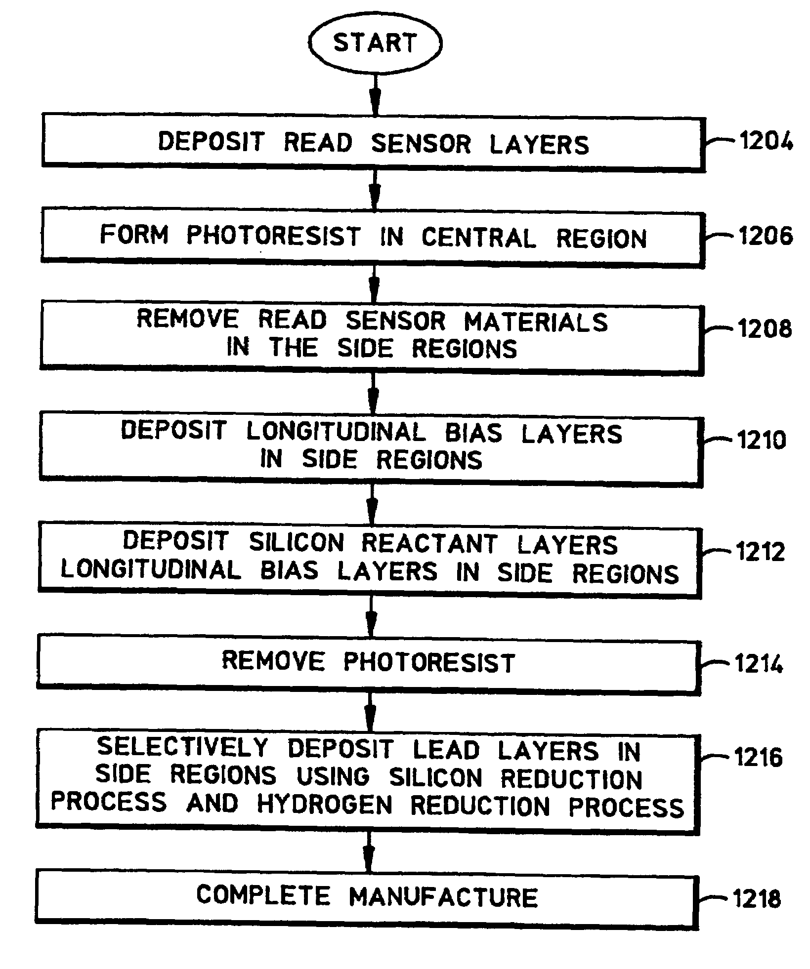
Method for use in making a read head
a technology of magnetoresistive and read head, which is applied in the manufacture of flux-sensitive heads, magnetic recording, information storage, etc., can solve the problems of difficult to remove monolayer photoresist, significantly reduce the stabilization efficiency of conventional bottom-type gmr sensors, and reduce the stabilization efficiency
- Summary
- Abstract
- Description
- Claims
- Application Information
AI Technical Summary
Benefits of technology
Problems solved by technology
Method used
Image

Examples
Embodiment Construction
[0035]The following description is the best embodiment presently contemplated for carrying out the present invention. This description is made for the purpose of illustrating the general principles of the present invention and is not meant to limit the inventive concepts claimed herein.
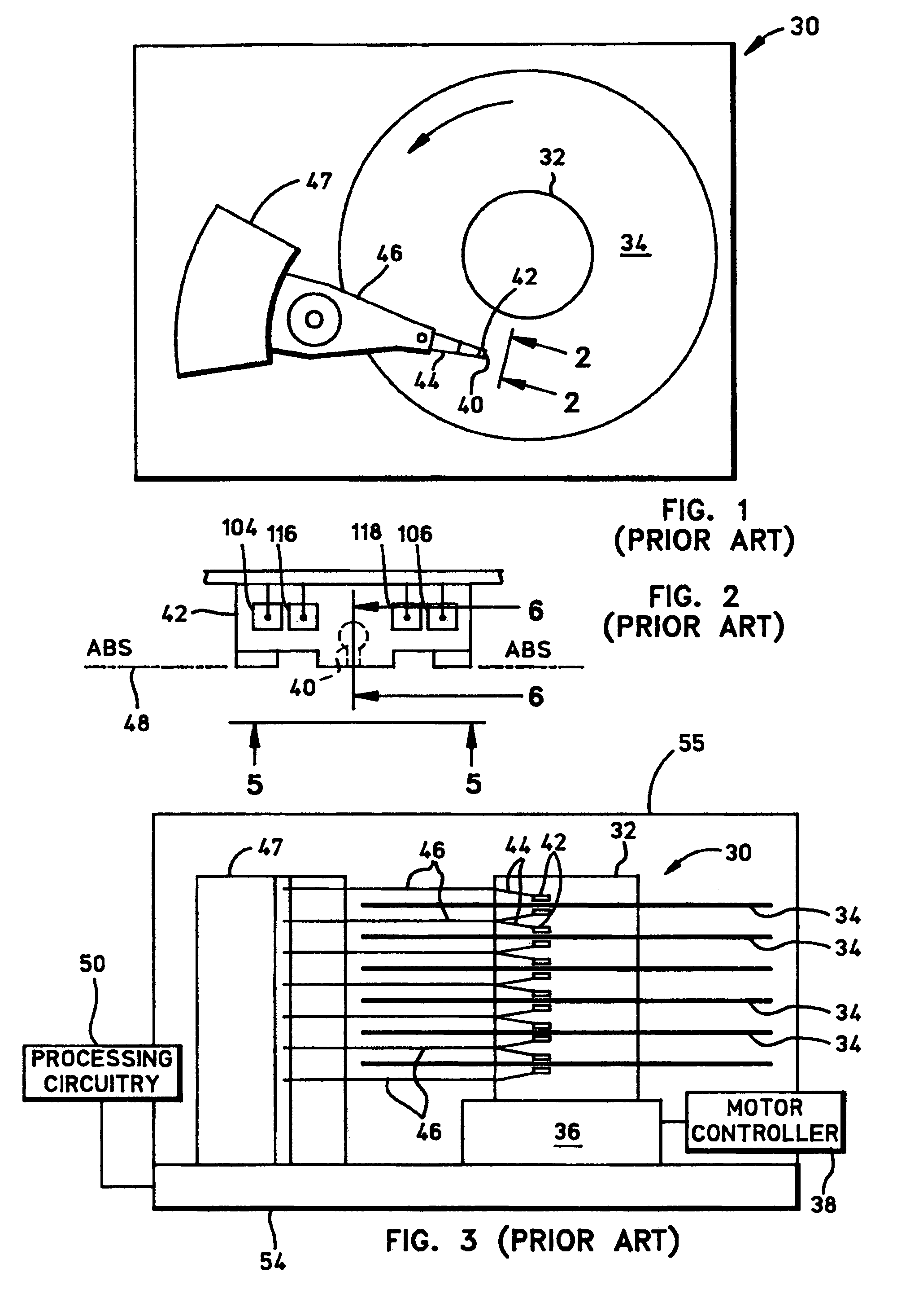
[0036]Referring now to the drawings wherein like reference numerals designate like or similar parts throughout the several views, FIGS. 1-3 illustrate a magnetic disk drive 30. Disk drive 30 includes a spindle 32 that supports and rotates a magnetic disk 34. Spindle 32 is rotated by a spindle motor 36 that is controlled by a motor controller 38. A slider 42 includes a combined read and write magnetic head 40 and is supported by a suspension 44 and actuator arm 46 that is rotatably positioned by an actuator 47. Magnetic head 40 may utilize the read sensor which is made in accordance with the present invention. A plurality of disks, sliders, and suspensions may be employed in a large capacity direct acc...
PUM
| Property | Measurement | Unit |
|---|---|---|
| thicknesses | aaaaa | aaaaa |
| thicknesses | aaaaa | aaaaa |
| thickness | aaaaa | aaaaa |
Abstract
Description
Claims
Application Information