Exhaust emission control system

a technology of exhaust gas and control system, which is applied in the direction of exhaust treatment electric control, lighting and heating apparatus, instruments, etc., can solve the problems of wasting energy and the longer time to arrive at the activation temperature of the catalyst, and achieve the effect of efficiently converting the thermal energy of exhaust gas into electric energy

Inactive Publication Date: 2008-12-23
TOYOTA JIDOSHA KK
View PDF17 Cites 30 Cited by
  • Summary
  • Abstract
  • Description
  • Claims
  • Application Information

AI Technical Summary

Benefits of technology

[0008]An object of the present invention is therefore to provide an exhaust emission control system capable of efficiently converting thermal energy of exhaust gas into electric energy, without slowing the arrival of the catalyst at the activation temperature.

Problems solved by technology

Exhaust gas from an automobile engine possesses thermal energy and discharge of exhaust gas results in wasting energy.
If the heat in exhaust gas is used for generation of electricity, there will arise a problem that the time to arrival of the catalyst at the activation temperature becomes longer, so as to delay the exertion of the purifying action.

Method used


Image

  • Exhaust emission control system
  • Exhaust emission control system
  • Exhaust emission control system

Examples


Embodiment Construction

[0036]The preferred embodiments of the present invention will be described below with reference to the drawings. Throughout the embodiments, parts having the same functionality will be denoted by the same reference symbols, without redundant description thereof.

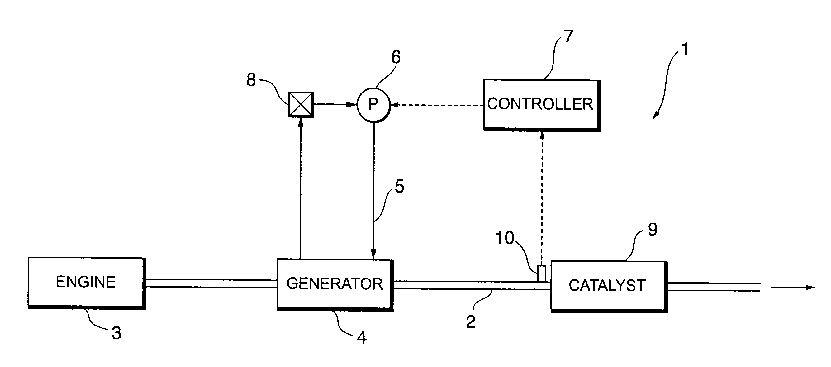
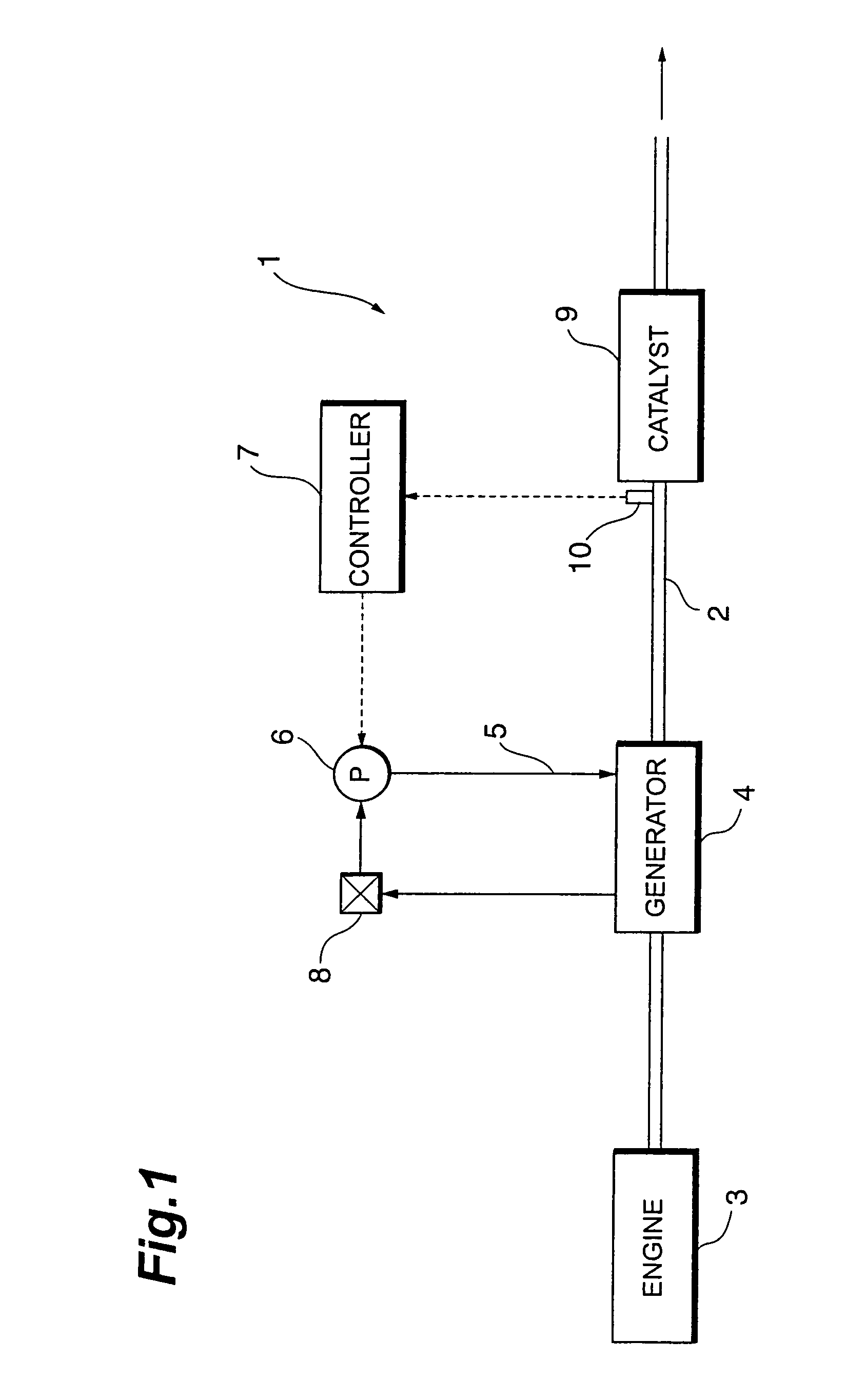
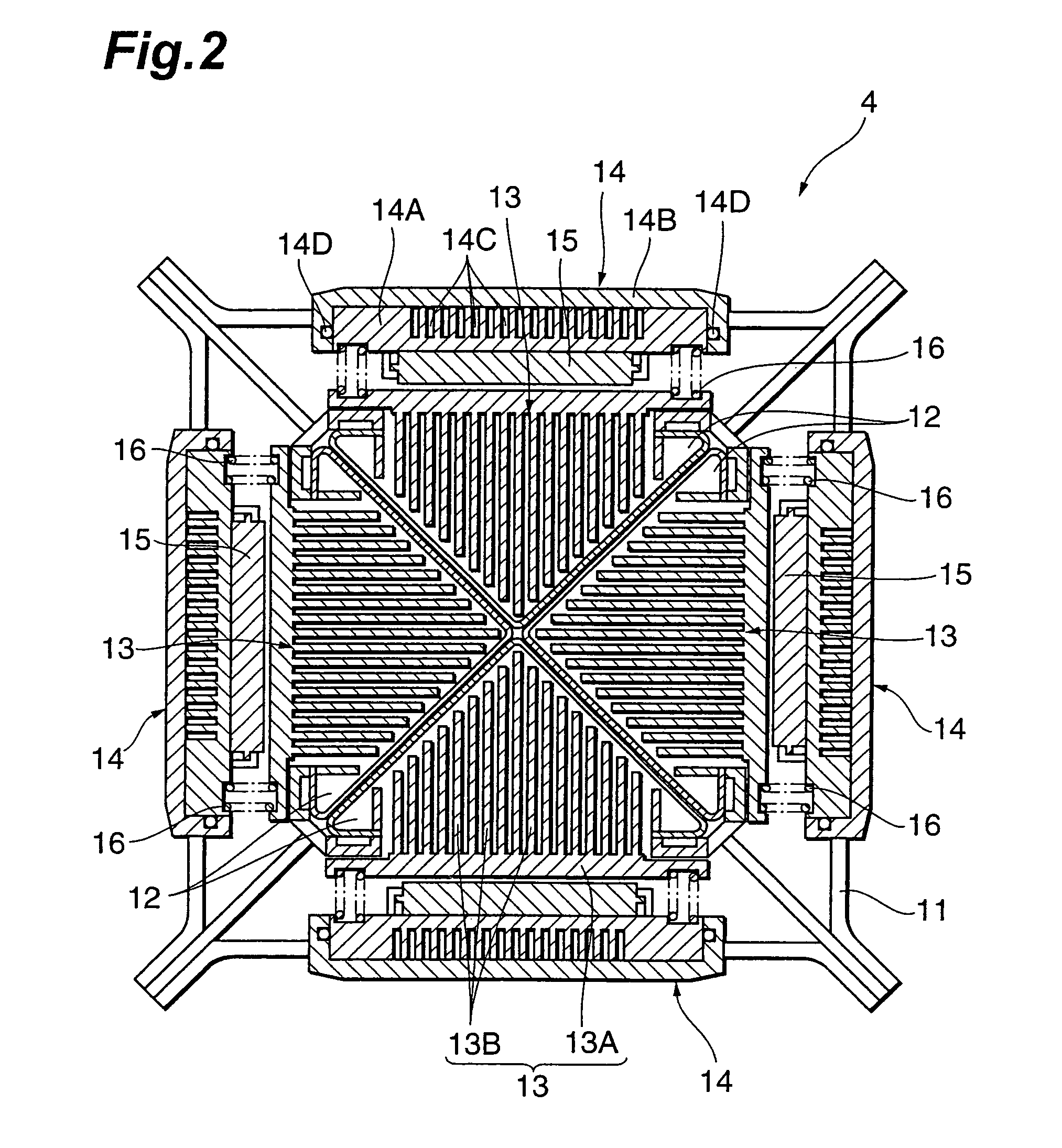
[0037]FIG. 1 is a block diagram of an exhaust emission control system according to an embodiment of the present invention, and FIG. 2 is a cross-sectional plan view of a generator (a cross section by a plane perpendicular to the flow of exhaust gas).

[0038]As shown in FIG. 1, the exhaust emission control system 1 of the present embodiment has an exhaust pipe 2. The exhaust pipe 2 is connected to an engine 3, and exhaust gas from the engine 3 flows in the exhaust pipe 2 to be discharged from an unrepresented muffler to the outside.

[0039]A generator 4 is provided midway on the exhaust pipe 2. The generator 4 converts thermal energy of exhaust gas into electric energy. A pump 6 for circulating a coolant through a coolant pipe 5 i...


PUM


Abstract

An exhaust emission control system.A generator has a thermoelectric conversion element for achieving thermoelectric conversion by making use of heat of exhaust gas. An exhaust purifying catalyst disposed in the generator or on the exhaust downstream side of the generator, and a heat conduction varying device make heat conduction from the exhaust gas to the thermoelectric conversion element variable between a high conduction state and a low conduction state. When a temperature of the exhaust purifying catalyst is higher than a predetermined temperature, the heat conduction varying device varies the heat conduction from the exhaust gas to the thermoelectric conversion element into the high conduction state. This permits the system to efficiently re-collect thermal energy from the exhaust gas and convert it into electric energy, without increase in a time to arrival of the exhaust purifying catalyst at an activation temperature thereof.

Description

BACKGROUND OF THE INVENTION[0001]1. Field of the Invention[0002]The present invention relates to an exhaust emission control system having a generator for converting thermal energy of exhaust into electric energy, and an exhaust purifying catalyst.[0003]2. Related Background Art[0004]Exhaust gas from an automobile engine possesses thermal energy and discharge of exhaust gas results in wasting energy. There is thus an electric generator configured to convert the thermal energy of exhaust gas into electric energy to charge a battery. An example of such generator is disclosed in Japanese Patent Application Laid-Open No. 2000-35824.[0005]This generator has a thermoelectric conversion element provided on an exhaust pipe, and a bimetallic element as a thermal connection means for conducting heat from the exhaust pipe to the thermoelectric conversion element. While the temperature of the exothermic member (exhaust pipe) is below an allowable temperature limit of the thermoelectric conversi...

Claims


Application Information

Patent Timeline
Patent Type & Authority Patents(United States)
IPC IPC(8): F01N3/02F01N3/20F01N3/24F01N5/02F01N11/00F02G5/02F02G5/04F28F27/00H01L35/00H01L35/30H02N11/00
CPCF01N3/02F01N3/0205F01N5/025F01N11/00H01L35/00F01N3/20F01N2240/04Y02T10/16Y02T10/20Y02T10/47Y02T10/12Y02T10/40H10N10/00
Inventor SASAKI, TOSHITAKEMURATA, KIYOHITO
Owner TOYOTA JIDOSHA KK
Why Eureka
Try Eureka