Nebulizer for ultrasonic humidifier

a technology of ultrasonic humidifier and nebulizer, which is applied in air humidification systems, lighting and heating apparatus, heating types, etc., can solve the problems of deterioration in the efficiency of the vibrator within a short time period, damage to the vibrator, and lowering the efficiency of the vibrator, so as to reduce the volume of the ultrasonic humidifier, prolong the life of the heat sink and the vibrator, and easily replace the vibrator

Inactive Publication Date: 2008-12-23
DOBOT ELECTRONICS +1
View PDF10 Cites 18 Cited by
  • Summary
  • Abstract
  • Description
  • Claims
  • Application Information

AI Technical Summary

Benefits of technology

[0016]Accordingly, the present invention has been made to solve the above-mentioned problems occurring in the prior art, and an object of the present invention is to provide a nebulizer for an ultrasonic humidifier which can prolong the lifetime of a heat sink and a vibrator, can reduce the volume of the ultrasonic humidifier, and can easily replace a vibrator, by employing a heat sink of improved corrosion resistance and integrating a water level sensor with the heat sink.
[0017]It is another object of the present invention to provide a nebulizer for an ultrasonic humidifier which has an LED mounted to the upper surface of a heat sink to radiate light outward through a transparent or translucent cover, so that the nebulizer has an appealing appearance.
[0019]A nebulizer for an ultrasonic humidifier according to the present invention is characterized in that the corrosion resistance thereof is improved and the ultrasonic humidifier can be easily cleaned by using the heat sink formed of brass and plated with nickel. Further, a nebulizer for an ultrasonic humidifier according to the present invention is characterized in that a water level sensor and an LED can be easily engaged by using a water tank assembling flange at the upper end portion of a holder for mounting the heat sink and thus completely exposing the upper surface of the heat sink to the outside. Furthermore, a nebulizer for an ultrasonic humidifier according to the present invention is characterized in that a vibrator is simply disassembled and changed with a water tank without separating a bottom plate of a humidifier, by inserting and assembling a vibrator guide, to which a vibrator is mounted, into and with a heat sink.
[0022]Therefore, it is a heat sink that is directed to prevent the PCB from being damaged by the heat, by irradiating the heat generated in the PCB outward. As mentioned above, it is preferable that the heat sink is formed of brass so that it enables prompt heat transfer and has corrosion resistance to water, bubbles, and impurities which may be contained in water. It is also preferable that a smooth nickel plating later is coated on the surface of the heat sink so that the impurities attached on the surface of the heat sink can be easily removed as the in-use time of the humidifier elapses.
[0023]Further, it is good for the appearance of the humidifier to allow the light irradiated from an LED assembled with the upper surface of the heat sink to be seen from outside of the humidifier, by assembling at least one LED with the upper surface of the heat sink exposed to the outside and by manufacturing an outer cover of the humidifier with a transparent or translucent material.

Problems solved by technology

The heat sink functioning as a final heat transferring medium, which radiates outward the heat generated in the ultrasonic oscillation circuit, is conventionally manufactured of an aluminum alloy coated with Teflon, which causes various problems, such as deterioration in the efficiency of the vibrator within a short time period.
Namely, since bubbles are generated not only in the vibrator but also on the surface of the heat sink during the operation of the humidifier, the surface of the heat sink of aluminum is easily corroded by the bubbles.
Further, since aluminum chips exfoliated from the surface of the heat sink produce scales when combined with together with various components contained in the water and the scales are stuck to the surface of the vibrator, the efficiency of the vibrator is lowered and the vibrator is damaged.
Therefore, the minute aluminum chips are discharged through a nebulizing nozzle together with vapor, thereby doing harm to human bodies.
Further, since water leakage toward the ultrasonic oscillation circuit side through a vibrator assembling portion is generated by the scales continuously accumulated on the surfaces of the heat sink and the vibrator, electrical short can be generated by the water, causing the entire nebulizer to be out of order.
In addition, according to the ultrasonic humidifier, since the nebulizer and the water level sensor are separately installed, the number of parts is increased, thereby raising the manufacturing costs.
Further, since too much area is necessary for installation of the nebulizer and the water level sensor, it is difficult to reduce the volume of the humidifier itself.

Method used


Image

  • Nebulizer for ultrasonic humidifier
  • Nebulizer for ultrasonic humidifier
  • Nebulizer for ultrasonic humidifier

Examples


Embodiment Construction

[0033]The object, technical constitution, operation, and effect of the present invention will be apparently understood by the following description with reference to the drawings showing a preferred embodiment of the present invention.

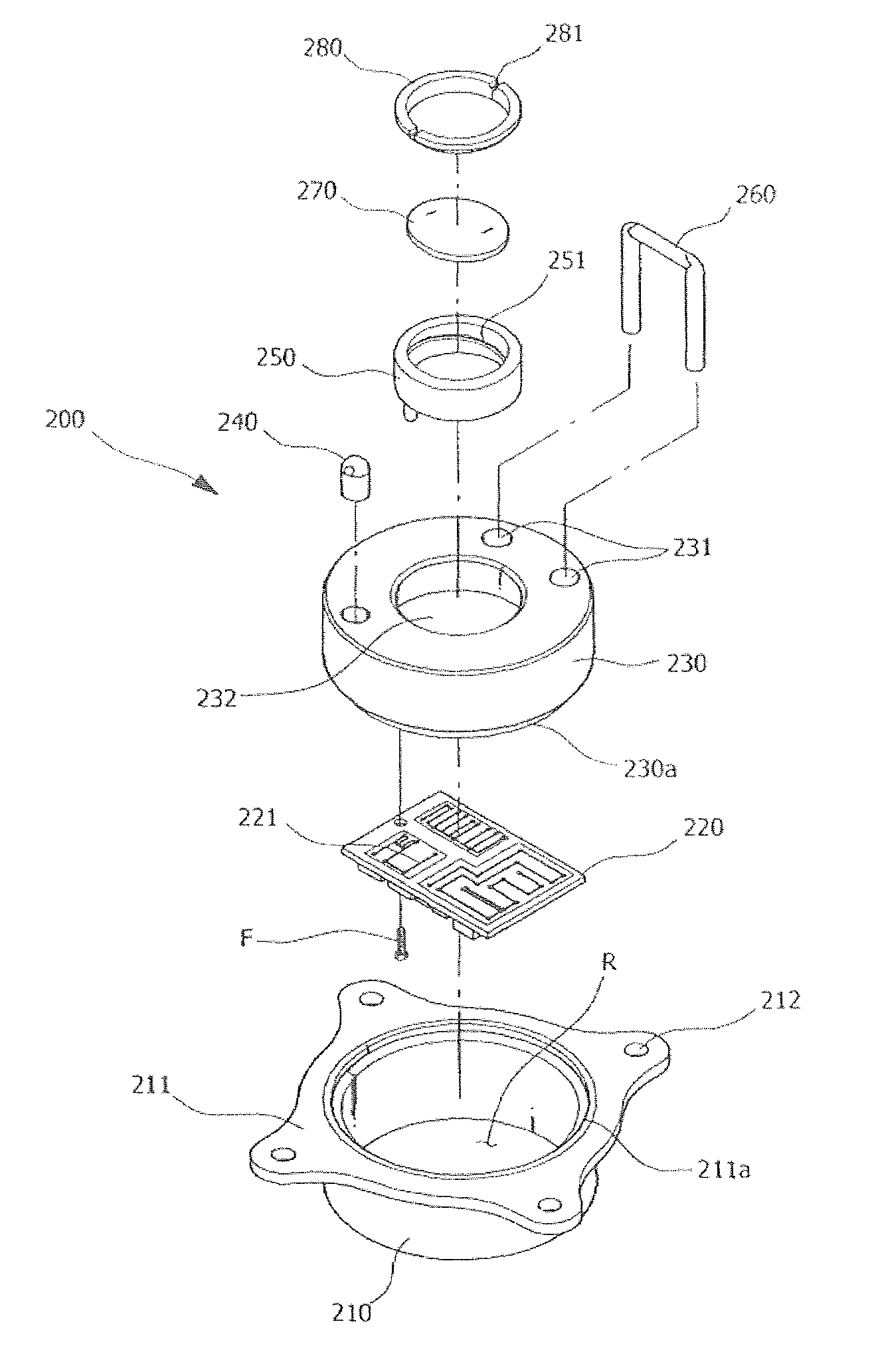
[0034]FIG. 3 is a partially cutaway perspective view for showing an ultrasonic humidifier employing a nebulizer according to a preferred embodiment of the present invention. FIG. 4 is a perspective view for showing the nebulizer according to the preferred embodiment of the present invention. FIG. 5 is an exploded perspective view for showing the nebulizer according to the preferred embodiment of the present invention. FIG. 6 is a cross-sectional view for showing the nebulizer according to the preferred embodiment of the present invention.

[0035]As shown in the figures, a nebulizer according to the present invention includes: a cylindrical heat sink holder 210 in which a flange 211 having a plurality of assembling holes 212 is provided at an upper end po...


PUM


Abstract

Disclosed is a nebulizer mounted to an ultrasonic humidifier. In the nebulizer, a heat sink holder can be directly connected to one side of a bottom plate in the humidifier, by using a flange provided at the upper end portion of the heat sink holder to which a heat sink for irradiating the heat generated in a PCB outward is mounted. Further, a vibrator assembled with the heat sink can be easily separated and replaced, because the heat sink is stacked on and assembled with the heat sink holder. Furthermore, the size of the ultrasonic humidifier is reduced, because a water level sensor is assembled and integrated with the upper surface of the heat sink. Furthermore, the durability of a vibrator as well as the heat sink is improved, because the heat sink is made of brass coated with a nickel plating layer.

Description

BACKGROUND OF THE INVENTION[0001]1. Field of the Invention[0002]The present invention relates to a nebulizer for an ultrasonic humidifier in which a heat sink assembled with a vibrator for nebulizing water for the ultrasonic humidifier is made of brass plated with nickel and a water level sensor is integrally assembled with the upper surface of the heat sink, so that the corrosion resistance of a heat sink is improved and the volume of the humidifier can be reduced.[0003]2. Description of the Prior Art[0004]A humidifier is a home appliance for maintaining pleasant interior surroundings by humidifying the dry interior air of a high temperature, especially, in the winter season. The humidifier is classified into a heating humidifier, an ultrasonic humidifier, a fan type humidifier, a hybrid type humidifier which uses advantages of the above-mentioned humidifiers, and the like.[0005]The heating humidifier generates vapor by heating water with a heater or an electrode rod, the ultrasoni...

Claims


Application Information

Patent Timeline
Patent Type & Authority Patents(United States)
IPC IPC(8): B01F3/04
CPCF24F6/02Y02B30/80Y10S261/48F24F2006/125Y02B30/70B05B17/0615F24F6/12F24F6/00F24F6/10
Inventor JAE-BONG, JEUNGDONG-MIN, JUNG
Owner DOBOT ELECTRONICS
Why Eureka
Try Eureka