Heatable container

a container and heat exchange technology, applied in the field of heat exchange containers, can solve the problems of significant time required to re-heat bitumen, product thermal shock, and severe deformation, so as to reduce heating period and heat energy, reduce heat shock, and enhance efficiency

Active Publication Date: 2008-12-23
CONT ASPHALT LTD
View PDF10 Cites 2 Cited by
  • Summary
  • Abstract
  • Description
  • Claims
  • Application Information

AI Technical Summary

Benefits of technology

[0007]The objects of the present invention are generally to overcome or at least minimize the problems with conventional systems which are set out above, namely, to minimize thermal shock to which the product is subjected, to enhance their efficiency, to reduce the heating period and the heat energy required.
[0008]It is a further object of this invention to provide a heatable container wherein the contents of the container is heated from the outside of the mass of the product, so as to prevent the contents of being exposed to thermal shock.

Problems solved by technology

Problems which are associated with conventional bitumen heating systems are well recognised and can be summarized as follows:(i) During re-heating of a bitumen-type product with conventional systems, the product is subjected to thermal shock and can become severely degraded.
Such degraded bitumen becomes unsuitable for road and pavement surfaces and results in early deterioration, as the thermal shock results in formation at micro fissures in such surfaces due to the change of the ductility of the bitumen.(ii) As mentioned above, because bitumen is a poor conductor of heat, a considerable period of time is required to re-heat the bitumen.
The long heating period which is required with conventional systems is also to a large degree attributable to the inefficiency of such systems.(iii) Because of the long heating period described in (ii) above, a considerable amount of energy in the form of heating fuel is required to bring the bitumen to the required temperature.
Such fuel costs can form a significant part of the cost of civil construction.

Method used


Image

  • Heatable container
  • Heatable container
  • Heatable container

Examples


Embodiment Construction

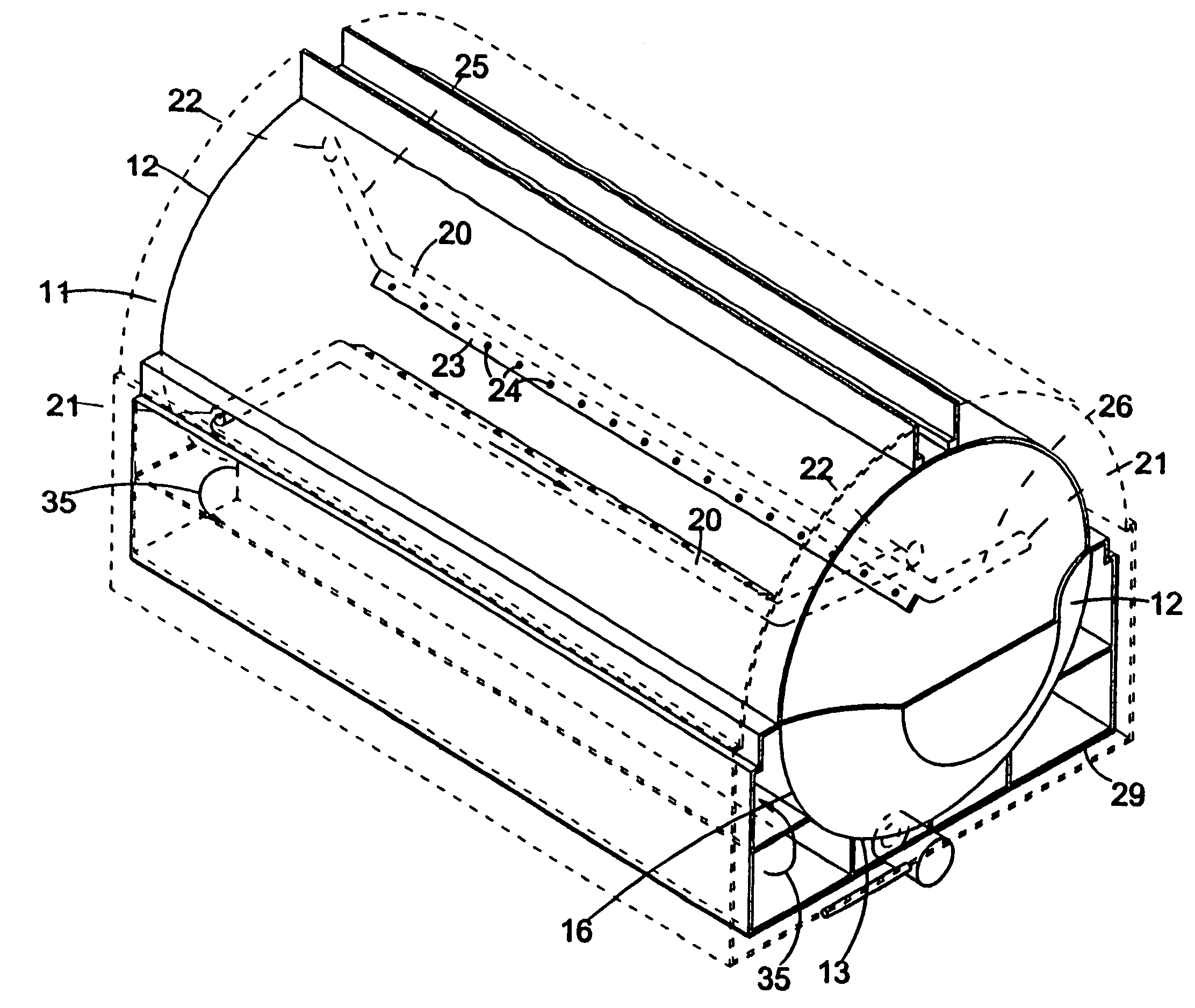
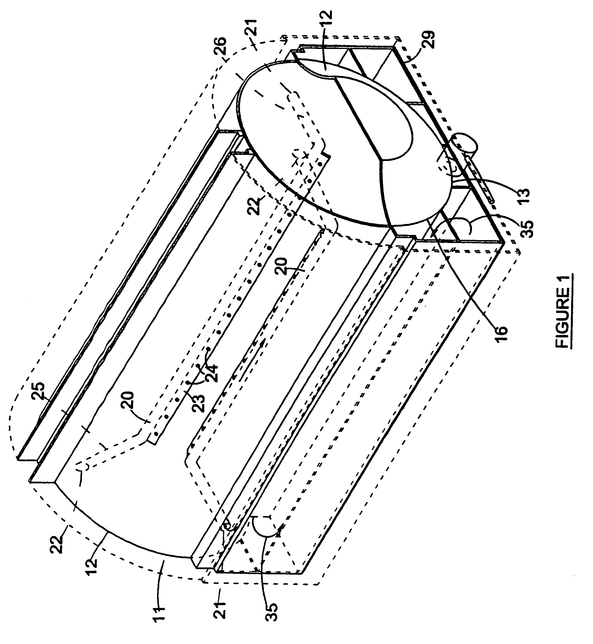
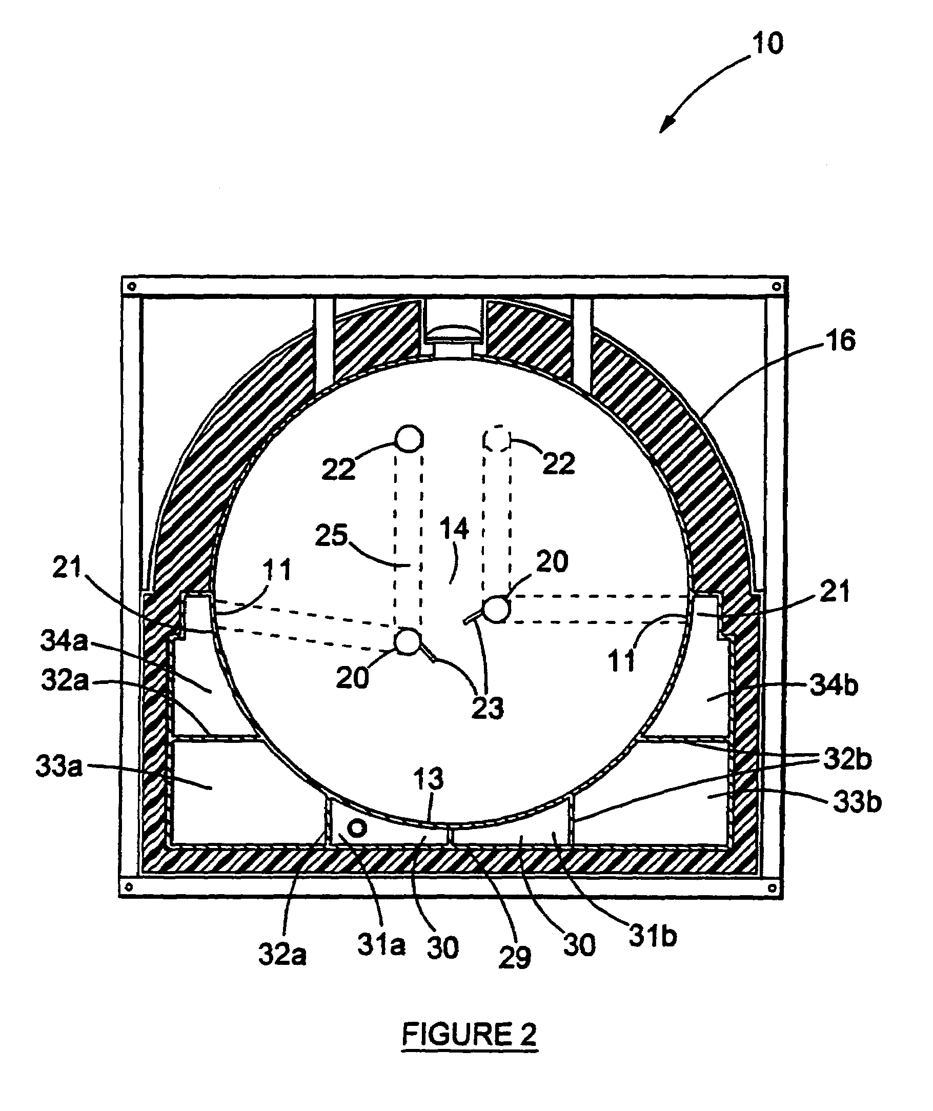
[0036]Referring to the drawings, in which like numerals indicate like features, a heatable container is generally indicated by reference numeral 10. The heatable container includes a vessel 16 in the form of an elongate cylinder, which includes side wall zones 11, end wall zones 12 in the form of dome-shaped ends, as well as a base wall zone 13.

[0037]Referring to FIGS. 1 and 2 the heatable container 10 typically includes a system of heating means for transferring heat to the content of the container, for example bitumen. The heating means include internal heating ducts 20 as well as external heating ducts 30. The external and internal heating ducts are in flow communication, and are connected in series so that a heat transfer medium first enters the external heating ducts 30 and thereafter the internal heating ducts 20. Two sets of heating means are furthermore associated with the heatable container, the two sets functioning in parallel and each set being in contact with one halve o...


PUM

PropertyMeasurementUnit
lengthaaaaaaaaaa
heataaaaaaaaaa
viscousaaaaaaaaaa

Abstract

A heatable container suitable for material such as bitumen. The container includes a vessel for holding a flowable material having side wall zones, end wall zones and a base wall zone. The container also includes a heating system for transferring heat to at least the base wall zone as well as a zone disposed along a central longitudinal axis of the vessel. The heating system may also included at least two internal heating ducts for conveying a heat transfer medium, wherein the ducts are disposed substantially parallel relative to the central longitudinal axis of the vessel, and are vertically and horizontally spaced apart relative to one another.

Description

FIELD OF THE INVENTION[0001]This invention relates to a heatable container, and more particularly, but not exclusively, to a heatable container suitable for heating and transportation of oil refinery residues, bitumen, cut back or similar products (like waxes) which allows the efficient heating of such products without unacceptable degradation due to thermal shock or overheating.BACKGROUND TO THE INVENTION[0002]Various applications exist where substances, being in the solid phase when under ambient conditions, must be melted in order to be used, or where such substances must be transported in a molten condition. This scenario is for instance encountered when working with bitumen. Bitumen is a viscous substance that is typically used for road surfacing, waterproofing (for instance in tunnels and dams) or roofing. The bitumen must be applied in the liquid phase, i.e. a molten condition, and is then allowed to coagulate once applied. It will be appreciated that it will be advantageous ...

Claims


Application Information

Patent Timeline
Patent Type & Authority Patents(United States)
IPC IPC(8): H05B3/02F24C5/00
CPCB65D88/128B65D88/744B65D88/748
Inventor GRISONI, JACQUES
Owner CONT ASPHALT LTD
Why Eureka
Try Eureka