
Integrated electrical power extraction for aircraft engines

a technology of aircraft engines and integrated electrical power, which is applied in the direction of electric generator control, machines/engines, transportation and packaging, etc., can solve the problems of large generators, detrimental engine performance, and no use of high-power pm generators on turbofan engines to da

Active Publication Date: 2008-12-23
GENERAL ELECTRIC CO
View PDF17 Cites 50 Cited by
  • Summary
  • Abstract
  • Description
  • Claims
  • Application Information

AI Technical Summary

Benefits of technology

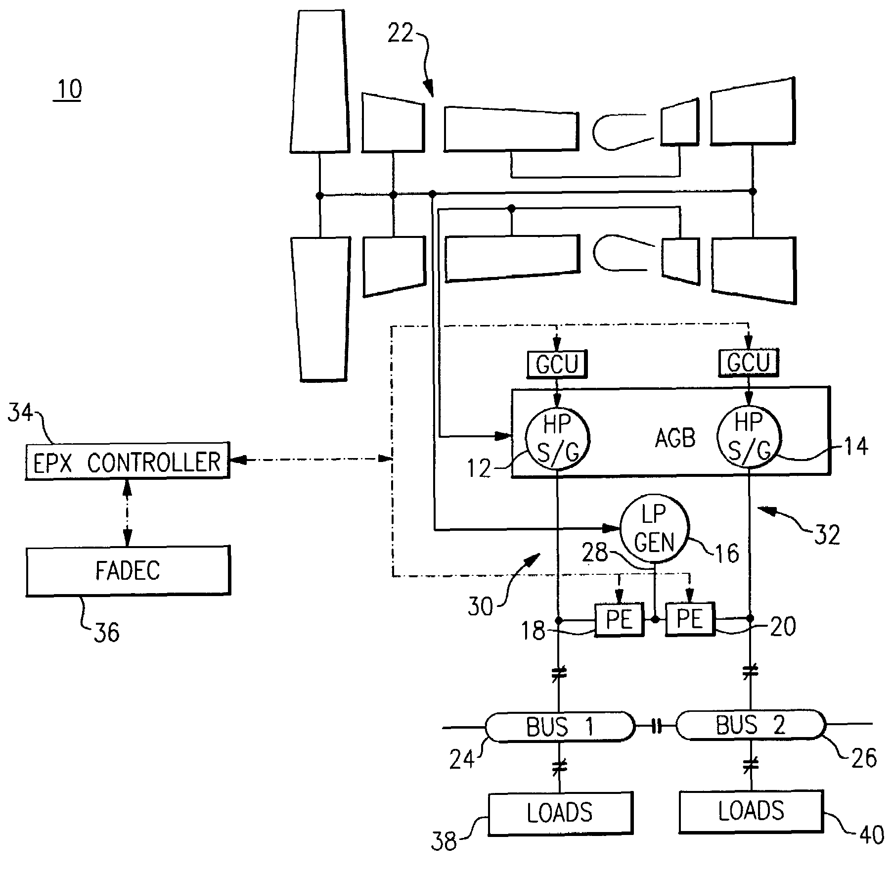
"The present invention is about an aircraft engine that has multiple engine spools and AC bus generators. Each AC bus generator is independently operational to supply AC power to a respective AC power bus. Additionally, there are at least one generator that is driven by a different engine spool and can provide additional AC power to each AC power bus in synchronization with the AC bus generators. The AC bus generators and the at least one generator can be directly driven to provide variable frequency power. The invention allows for more efficient and flexible power distribution in an aircraft engine."

Problems solved by technology

These increased electrical demands require larger generators to supply the additional electrical power.
However, this added load placed on the HP engine core, can have a detrimental effect on engine performance under certain conditions.
There has been however, no use of high power PM generators on turbo fan engines to date, for reasons of cost, complexity, and unproven technology, among other things.
Although 400 Hz systems often run in parallel (aka, military transports and B747-400), variable frequency generators however (non-400 Hz), are not seamlessly paralleled or integrated with one another.
These methods and systems are not seamlessly integrated with an aircraft power system.
This technology is not seamlessly integrated with an aircraft power system.
These approaches disadvantageously require significant integration with an airframe power system, and are not seamlessly integrated with the airframe power system.

Method used


Image

  • Integrated electrical power extraction for aircraft engines
  • Integrated electrical power extraction for aircraft engines
  • Integrated electrical power extraction for aircraft engines

Examples


Embodiment Construction

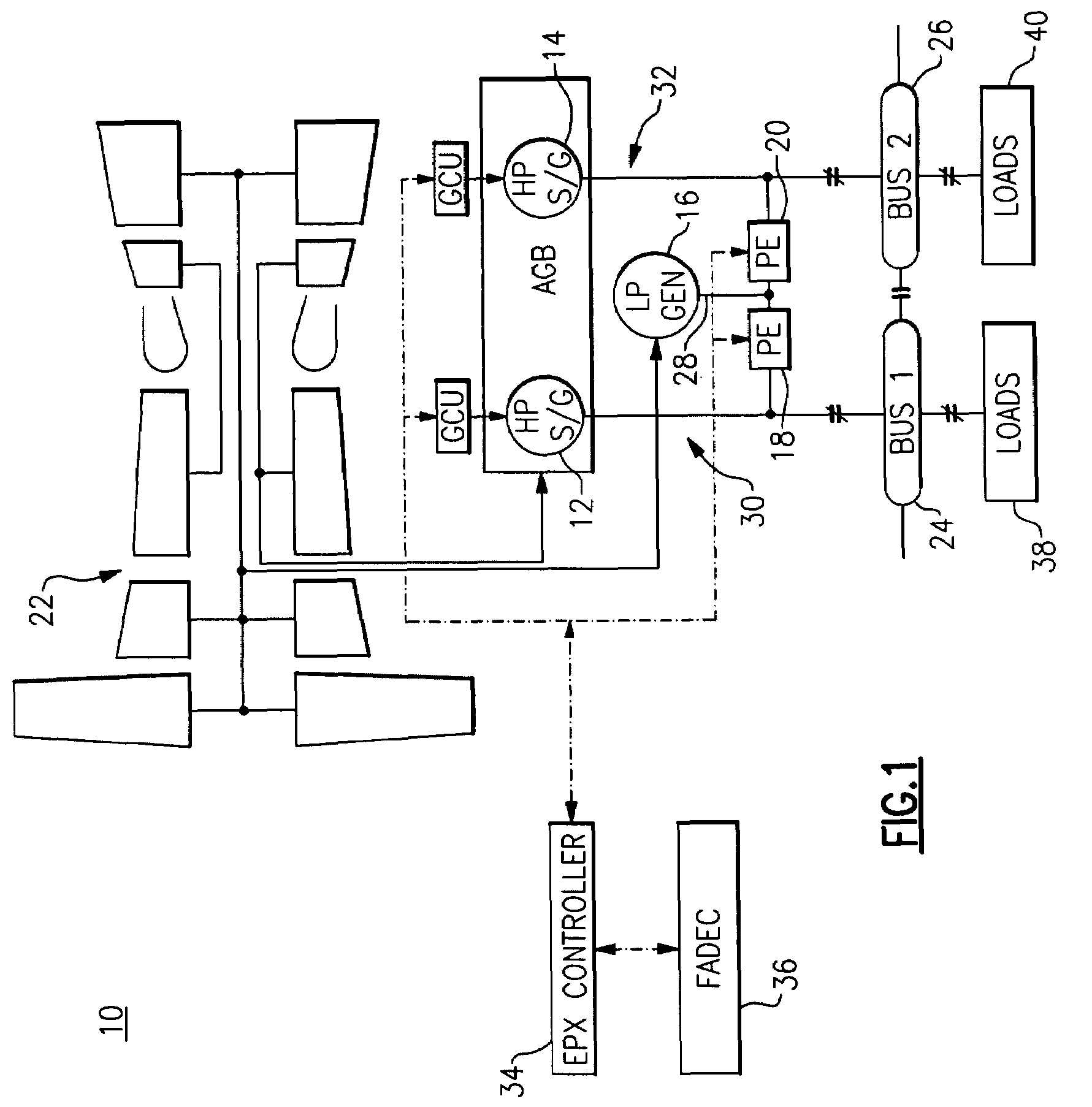
[0026]FIG. 1 illustrates a wild frequency electrical power extraction system architecture 10 with an externally located LP generator 16, according to one embodiment of the present invention. A key feature of the systems and methods described herein below is that these systems and methods enable the seamless integration of an LP generator with existing HP starter-generators, with transparency to an airframe power system (i.e., it is fully compatible with most commonly used aircraft power systems). Although some embodiments are described with reference to HP starter-generators, other embodiments may just as easily employ HP generators that do not provide a start function to achieve the desired results according to the principles discussed herein below.

[0027]With continued reference to FIG. 1, all of the HP starter-generators 12, 14, the LP generator 16, and power electronics (PE) 18, 20 associated with EPX system architecture 10 can be seen to be located externally to the engine 22. T...


PUM


Abstract

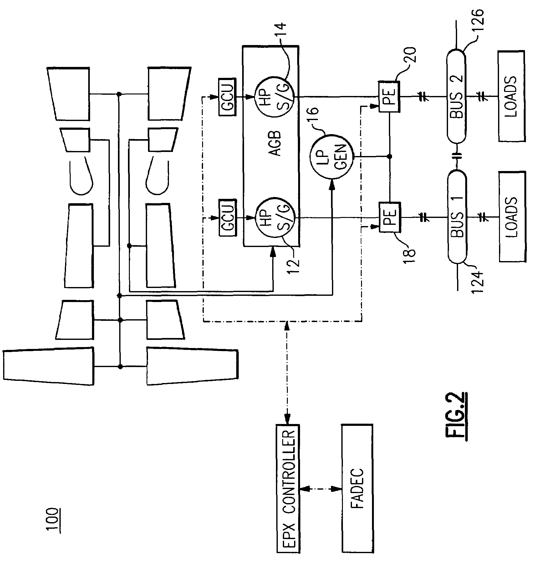
An aircraft power system includes an aircraft engine having a plurality of engine spools, a plurality of AC generators driven by at least one spool, wherein each AC generator is independently operational to supply AC power to a respective AC power bus or a respective power electronics module, and at least one generator driven by a different engine spool, wherein the at least one generator is operational to supply additional AC power to each AC power bus in synchronization with each respective AC generator, or to supply additional AC power to each power electronics module in parallel with the AC power delivered to each power electronics module by the plurality of AC generators. The power electronics module(s) are operational to selectively provide either AC or DC power to desired distribution buses. Each AC generator and the at least one generator may be responsive to commands from an electrical power extraction (EPX) controller. At least one generator may be directly driven to provide variable frequency power.

Description

BACKGROUND[0001]The present invention is directed to electrical power extraction from aircraft engines, and more particularly to an electrical power generation system which enables efficient and dynamic production of electrical power from a turbofan engine.[0002]Individual components of turbofan engines require different power parameters during operation. The fan rotational speed, for example, is limited to a degree by the tip velocity and, since the fan diameter is very large, rotational speed must be relatively low. The core compressor, on the other hand, because of its much smaller tip diameter, can be driven at a higher rotational speed. Therefore, separate high and low speed turbines with independent power transmitting devices are necessary for the fan and core compressor in aircraft gas turbine engines. Furthermore since a turbine is most efficient at higher rotational speeds, the lower speed turbine driving the fan requires additional stages to extract the necessary power.[00...

Claims


Application Information

Patent Timeline
Patent Type & Authority Patents(United States)
IPC IPC(8): F02B63/04H02K7/18
CPCH02P9/302H02P2101/30
Inventor KERN, JOHN MICHAELWIEGMAN, HERMAN LUCAS NORBERT
Owner GENERAL ELECTRIC CO
Learn More