Wind turbine

a wind turbine and blade extension technology, applied in the direction of wind turbines, machines/engines, wind energy generation, etc., can solve the problem that the structural disadvantage only entails negligible additional weight, and achieve the effect of reducing additional, heavy and expensive blade extenders

Active Publication Date: 2008-12-30
SIEMENS GAMESA RENEWABLE ENERGY SERVICE GMBH
View PDF6 Cites 25 Cited by
  • Summary
  • Abstract
  • Description
  • Claims
  • Application Information

AI Technical Summary

Benefits of technology

[0013]Accordingly the objective of the present invention is to avoid the drawbacks of the state of the art and to conceive and implement an especially economical configuration of rotor hub, blade bearing, rotor blade and adjustment drive whereby, employing a minimum of equipment / material jointly with a rigid and compact construction applying large blade adjustment torques. In particular the spatial configuration is selected in a manner that the hub shall be directly accessible.
[0015]Furthermore the adjustment drives point inward, i.e., the drive motor is mounted a smaller distance from the rotor axis of rotation than the distance between this axis and the drive pinion. This feature eliminates a main drawback, namely the increased danger of lightning strikes on outwardly pointing adjustment drives, namely in that the equipment of the invention is configured directly in front of the (metallic) rotor hub.
[0017]In the most advantageous case, the said rotation out of the central position allows using even coaxial blade adjustment drives, that is the drive pinions, the gearing unit, and the drive motor share substantially a common axis of symmetry. However, in crowded circumstances, angle drives also must be used, which however may be configured in a manner to allow access for maintenance through the front (away from the nacelle) access aperture to the inside of the hub. This design in particular allows eliminating additional, heavy and expensive blade extenders. The advantageous, rigidifying effects offered by blade extenders may now be assumed by an appropriate hub geometry, in a particularly advantageous manner by blade flange rigidification. In particular the embodiment of the invention when applied to conventional wind rotors with three rotor blades allows arraying the drives as an equilateral triangle without thereby restricting access through the access aperture.

Problems solved by technology

However contrary to all prior experience with such designs, it was discovered that such structurally disadvantageous shape only entails negligible additional weight which is fully compensated for by the advantageous configuration of the drives.

Method used


Image

  • Wind turbine
  • Wind turbine
  • Wind turbine

Examples


Embodiment Construction

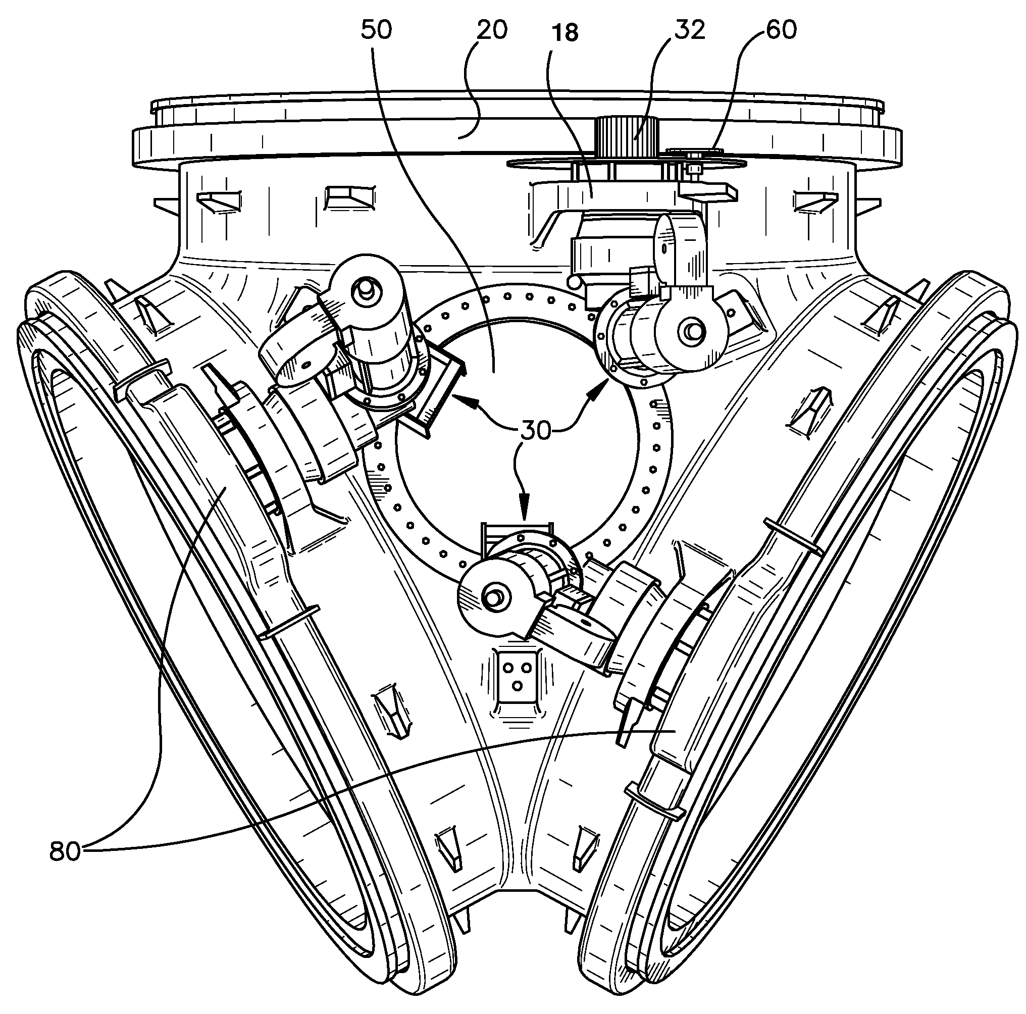
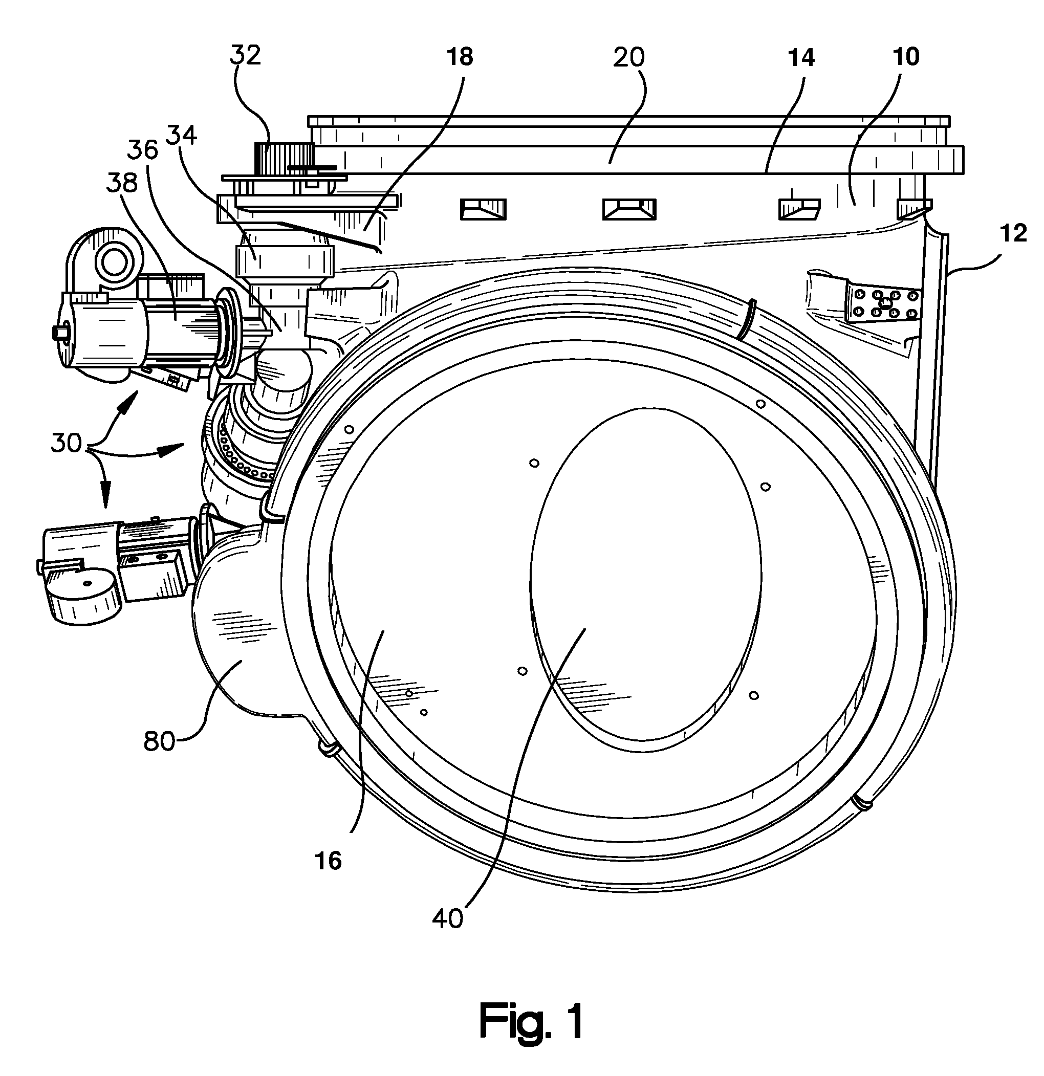
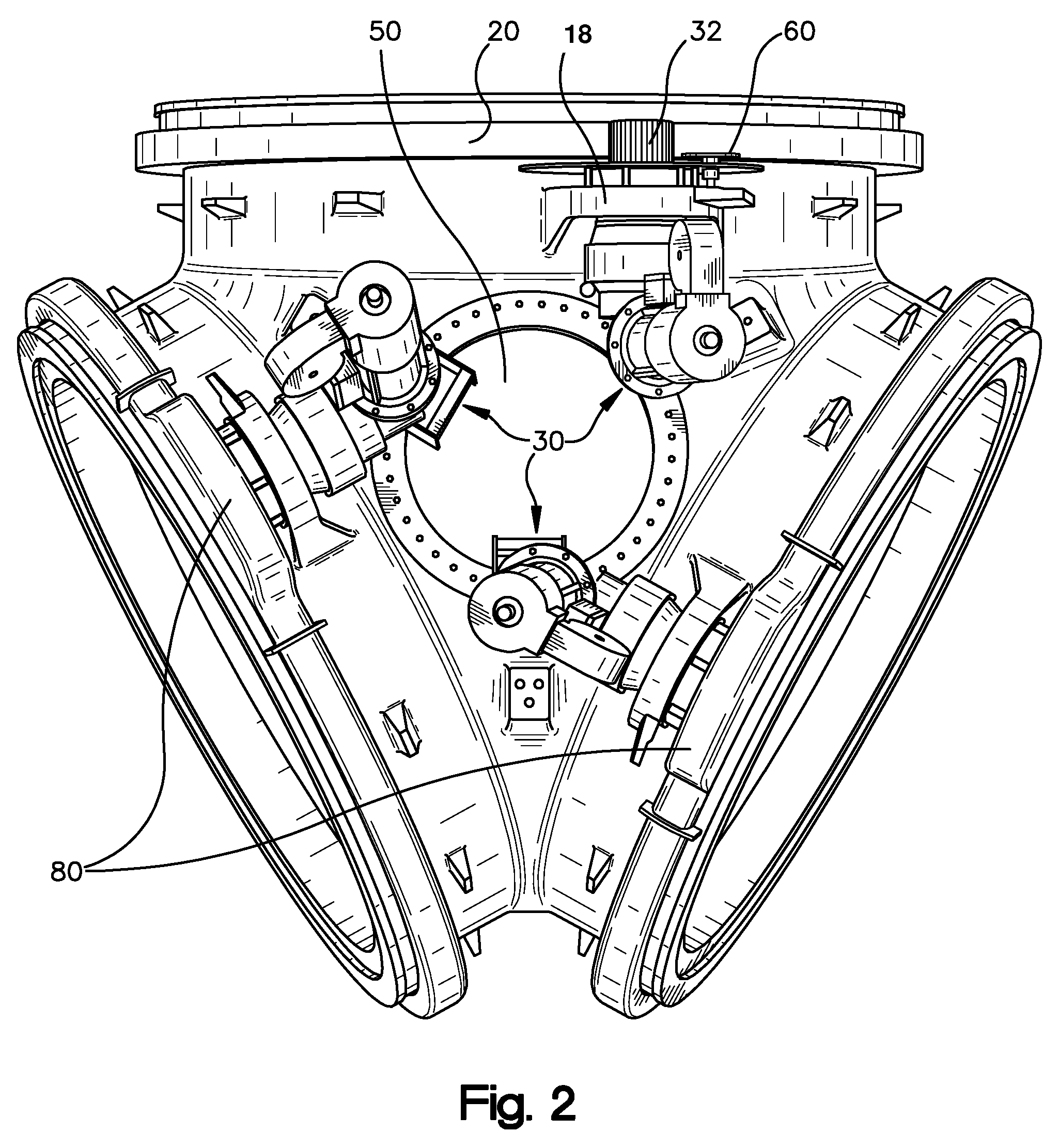
[0023]FIG. 1 is a side view of a rotor hub 10 having (a total of three) blade adjustment systems, each with one blade adjustment drive 30, of a wind turbine of the present invention. The shaft flange 12 connects to a rotor shaft supported in the nacelle. A blade bearing 20 is mounted on the blade flange 14. The blade adjustment drive 30 resting on a bracket 18 cast onto the hub comprises a drive pinion 32 meshing with the omitted external toothing of the blade bearing 20. Moreover the shown blade adjustment drive comprises a planetary gear unit 34 coaxial with the drive pinion and an angle gear 36 and a drive motor 38. A blade flange rigidifying means 16 fitted with a manhole 40 in this instance shown being elliptical is located in the lower part of the hub 10. This manhole 40 allows maintenance personnel to access—from the inside of the rotor hub 10—the omitted rotor blade. In the shown embodiment mode, the blade flange rigidifying means 16 is made integrally with the rotor hub, th...


PUM


Abstract

A wind turbine equipped with a tower, a nacelle rotatably mounted on the tower, a rotor rotatable at the nacelle about a rotor axis of rotation and including one rotor hub and at least one rotor blade which is coupled by a blade bearing to the rotor hub while rotatable about a blade adjustment axis. The blade bearing includes an inner ring firmly affixed to the rotor hub and an outer ring that is fitted with a toothing and that is firmly connected to the rotor blade. The rotor blade is rotatable by a blade adjustment drive including a drive motor actuating a drive pinion meshing with the outer toothing of the outer ring. On the rotor hub's side away from the nacelle, the drive pinion is configured at an angle of 10 to 30° as measured about the blade adjustment axis to a plane subtended by the rotor axis of rotation and the blade adjustment axis, and the drive motor is mounted at a distance from the rotor axis of rotation that is smaller than the distance between the drive pinion and the rotor axis of rotation.

Description

BACKGROUND OF THE INVENTION[0001]1. Field of the Invention[0002]The present invention relates to a wind turbine comprising at least one blade adjustment system.[0003]2. Description of the Related Art[0004]In wind turbines of this species, a rotor blade is rotatably affixed with a blade bearing to a rotor hub. The blade adjustment system comprises at least one blade adjustment drive fitted with a drive pinion, a gear unit and an electric or hydraulic drive motor. The drive pinion meshes with the external or inner toothed blade bearing.[0005]Such systems must meet several requirements which can be made technically compatible only with difficulties.[0006]In order to minimize the stresses applied to the adjoining structure, the rotor hub and the blade adjustment system should be both low in weight and economical in manufacture.[0007]On the other hand the blade bearing requires very rigid adjacent connection because warping the connecting flange would shorten bearing life.[0008]Moreover ...

Claims


Application Information

Patent Timeline
Patent Type & Authority Patents(United States)
IPC IPC(8): F03B11/00F03D1/00F03D1/06F03D7/00F03D7/02
CPCF03D1/0658F03D7/0224F03D11/0008F05B2240/40F05B2260/4031F05B2260/76F05B2260/79F05B2270/602Y02E10/721Y02E10/723Y02E10/722F03D80/70Y02E10/72
Inventor SCHUBERT, MATTHIAS
Owner SIEMENS GAMESA RENEWABLE ENERGY SERVICE GMBH
Why Eureka
Try Eureka