Liquid ejection head and image forming apparatus

a technology of liquid ejection and image forming apparatus, which is applied in piezoelectric/electrostrictive/magnetostrictive devices, piezoelectric/electrostriction/magnetostriction machines, printing, etc., can solve the problems of variation in the diameter of particles, difficulty in controlling the ejection direction, and unsuitability for high-viscosity liquids, so as to improve the control of the ejection direction and the effect of ejection volum

Inactive Publication Date: 2008-12-30
FUJIFILM CORP
View PDF4 Cites 17 Cited by
  • Summary
  • Abstract
  • Description
  • Claims
  • Application Information

AI Technical Summary

Benefits of technology

[0006]The present invention has been contrived in view of the foregoing circumstances, an object thereof being to provide a liquid ejection head and an image forming apparatus using same, whereby the control of the ejection direction and the ejection volume are improved, and viscous heat generation due to prolonged oscillation of a capillary wave can be prevented.
[0009]In this way, by forming a curved liquid surface by means of the surface tension of the liquid, in accordance with the conical surface shape section of the guide member, the capillary wave becomes able to propagate more readily in the direction of the longitudinal wave radiation angle (Rayleigh angle) on the basis of the leaky Rayleigh wave. Furthermore, since the apex section of the guide member forms the interface (triple point) between the three layers of the solid (the guide member), the liquid, and the gas (the air) (in other words, since the three-layer interface is formed into a singular point at the front tip of the guide member), then control over the ejection direction and the ejection volume is improved in comparison with the related art composition (namely, a composition in which no guide member is provided).
[0010]Moreover, in this aspect of the present invention, a particle formation mechanism based on amplification of a capillary wave, as used in the related art, is not used; therefore, it is possible to avoid viscous loading due to prolonged oscillation of a highly viscous liquid and to avoid the phase transition caused by same.
[0028]According to the present invention, a capillary wave propagates in accordance with the conical surface shape section of the guide member and a liquid particle is generated from the apex section of the conical surface shape section of the guide member, and therefore the control over the ejection direction and the ejection volume is improved. Moreover, by means of the particle forming mechanism according to the present invention, it is possible to avoid the problem of viscous heat generation in the highly viscous liquid and the problem of phase transition caused by such heat generation, as in the related art.

Problems solved by technology

However, in the former case (where a group of minute liquid droplets are drawn off from the vicinity of the three-phase interface), there is difficulty in controlling the ejection direction, and there is also variation in the diameter of the particles.
On the other hand, the latter case (based on the formation of a so-called capillary mist) uses a mechanism which amplifies the capillary wave on the liquid surface by parametric resonance, and therefore it is not suitable for high-viscosity liquids.

Method used


Image

  • Liquid ejection head and image forming apparatus
  • Liquid ejection head and image forming apparatus
  • Liquid ejection head and image forming apparatus

Examples


modification example

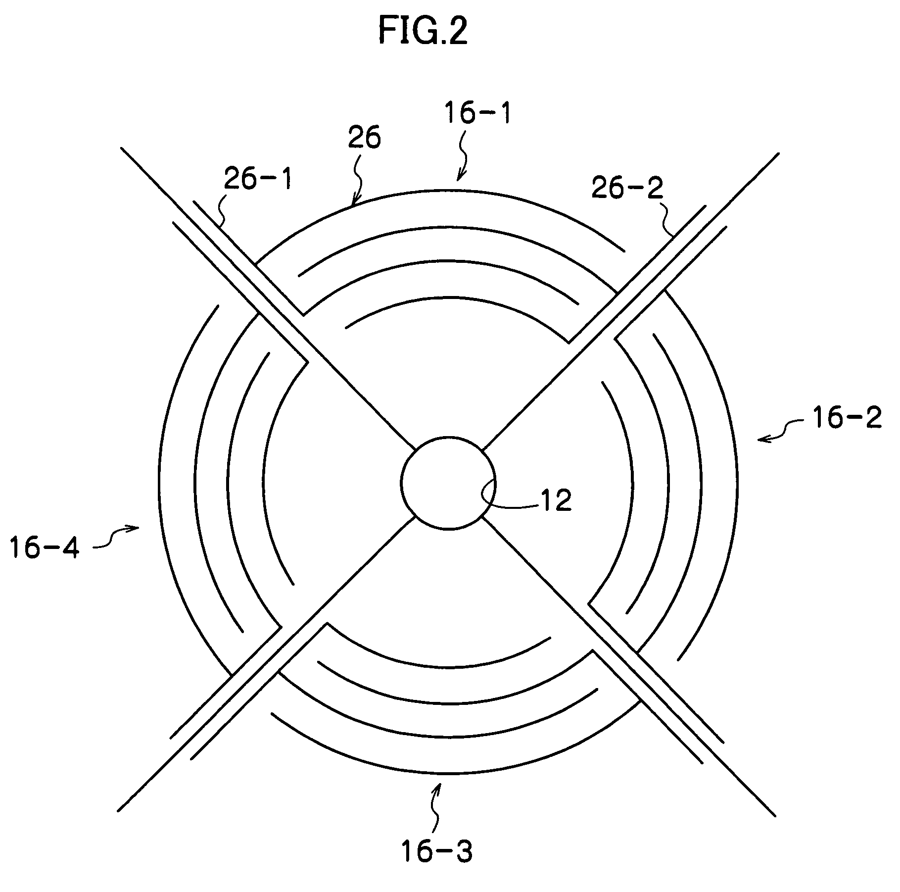
[0105]The embodiment described above relates to a mode where a conically shaped guide member is provided inside the circular nozzle, but the implementation of the present invention is not limited to this mode. For example, as shown in FIG. 11, it is possible to adopt a mode in which a square conical guide (quadrangular pyramid guide) 216 is provided in the center of a square-shaped nozzle orifice 212. In this case, IDTs 226 including comb-shaped electrodes 226-1 and 226-2 are provided so as to correspond with the four edges of the nozzle orifice 212.

[0106]The shape of the nozzle orifice and the cone shape (pyramid shape) of the guide member disposed in the center of the nozzle orifice are desirably shapes which have as little anisotropy as possible with respect to the central axis. Taking symmetry into consideration, generally, apart from a circular conical shape, a desirable mode is one in which a regular n-sided conical guide member (where n is an integer equal to or greater than ...


PUM


Abstract

The liquid ejection head has: a surface acoustic wave propagation body in which a surface acoustic wave propagates; a nozzle orifice formed in the surface acoustic wave propagation body; a surface acoustic wave generation device which is provided on the surface acoustic wave propagation body around the nozzle orifice and excites the surface acoustic wave propagation body so that a surface acoustic wave is generated in the surface acoustic wave propagation body; a liquid supply device which supplies liquid to the nozzle orifice; and a guide member which is provided in a center of the nozzle orifice and has a tapered conical surface shape section that projects from an ejection surface of the nozzle orifice in an ejection direction, the liquid forming a curved liquid surface in the nozzle orifice in accordance with the tapered conical surface shape section due to surface tension, wherein the surface acoustic wave generates a capillary wave which propagates through the curved liquid surface in the nozzle orifice and which ejects the liquid from an apex section of the tapered conical surface shape section.

Description

BACKGROUND OF THE INVENTION[0001]1. Field of the Invention[0002]The present invention relates to a liquid ejection head and an image forming apparatus, and more particularly, to a liquid ejection head which generates a minute liquid droplet from a liquid surface by means of a surface acoustic wave, and to an image forming apparatus which uses such a liquid ejection head.[0003]2. Description of the Related Art[0004]In the related art, Japanese Patent Application Publication No. 2000-62161 and Japanese Patent Application Publication No. 9-267473 disclose inkjet heads based on a method which ejects ink by emitting a surface acoustic wave (SAW) into ink. In a general surface acoustic wave type of head of this kind, when a surface acoustic wave (SAW, Rayleigh wave) is caused on the surface of a solid and this wave is introduced into a liquid by leaking, then either a group of minute liquid droplets are drawn off from the vicinity of the three-phase interface by a longitudinal wave radiat...

Claims


Application Information

Patent Timeline
Patent Type & Authority Patents(United States)
IPC IPC(8): H01L41/00B41J2/045
CPCB41J2/14008
Inventor ONOZAWA, SHO
Owner FUJIFILM CORP
Why Eureka
Try Eureka