
Method of finding a maximum power of a photovoltaic generator

a photovoltaic generator and power point technology, applied in the direction of electric variable regulation, process and machine control, instruments, etc., can solve the problems of partial shadowing, power output of a partially shadowed generator will not be at its maximum, and energy efficiency of the system as a whole to drop

Active Publication Date: 2008-12-30
SMA SOLAR TECH AG
View PDF6 Cites 42 Cited by
  • Summary
  • Abstract
  • Description
  • Claims
  • Application Information

AI Technical Summary

Benefits of technology

[0013]The invention makes it possible to increase the energy efficiency of a system consisting of a photovoltaic generator and a current power converter when the generator is partially shadowed and when conventional MPPT maximum regulation is doomed to fail because of a plurality of maxima in the characteristic curve of the generator.
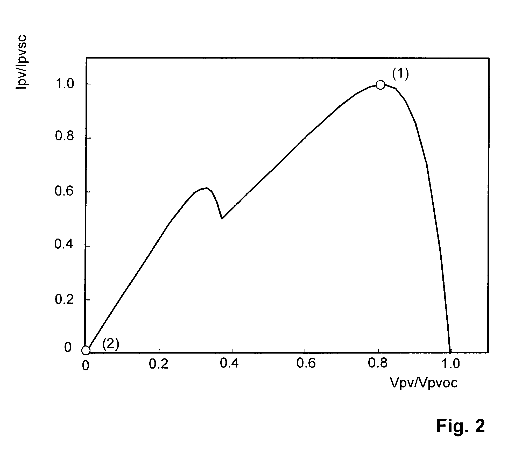
[0023]Another advantage is that, after interference in the regulation loops, the power of the power converter is reduced so that a first operating point of a power characteristic curve that corresponds to a global maximum moves toward a second operating point located near the generator's idle voltage. This permits setting a local right side power maximum.

Problems solved by technology

If a shadow falls onto the sensor or if part of the generator is shadowed, an operating point is created that will not supply maximum power, this causing the energy efficiency of the system as a whole to drop.
Therefore, it may happen that the power output by a partially shadowed generator will not be at its maximum and that part of the solar energy will not be used.
The disadvantage of this method also is that partial shadowing is not recognized.

Method used


Image

  • Method of finding a maximum power of a photovoltaic generator
  • Method of finding a maximum power of a photovoltaic generator
  • Method of finding a maximum power of a photovoltaic generator

Examples


Embodiment Construction

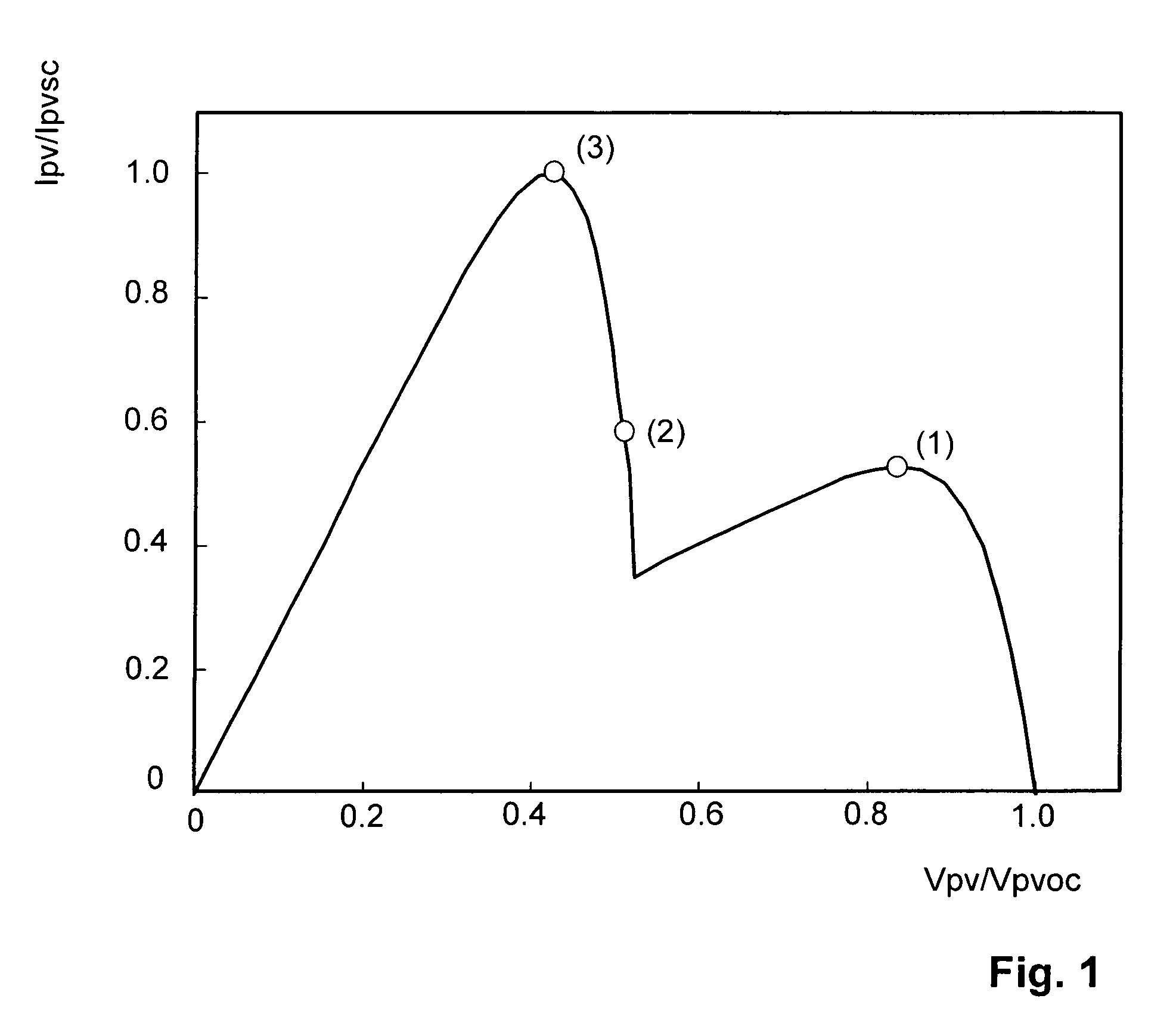
[0035]FIG. 1 shows a characteristic curve of a partially shadowed photovoltaic generator or rather of a generator array. An area portion of the generator is less irradiated by the sun because of a shadow or for another reason.

[0036]The characteristic curve has two maxima (1) and (3). The right maximum (1) is referred to as the local maximum, whilst the left maximum (3) is referred to as the global maximum. The left (global) maximum (3) is greater than the right (local) maximum.

[0037]Using a conventional MPP Tracking, a local power maximum (1) may occur since the various power maxima cannot be distinguished. As a result, part of the solar energy is not made use of and the energy efficiency of the array drops considerably.

[0038]Conventional MPPT preferably operate, constantly tracking and moving around a local power maximum.

[0039]Global Left Side Maximum

[0040]The instance just discussed and the functioning of the invention will now be discussed in greater detail.

[0041]The invention ma...


PUM


Abstract

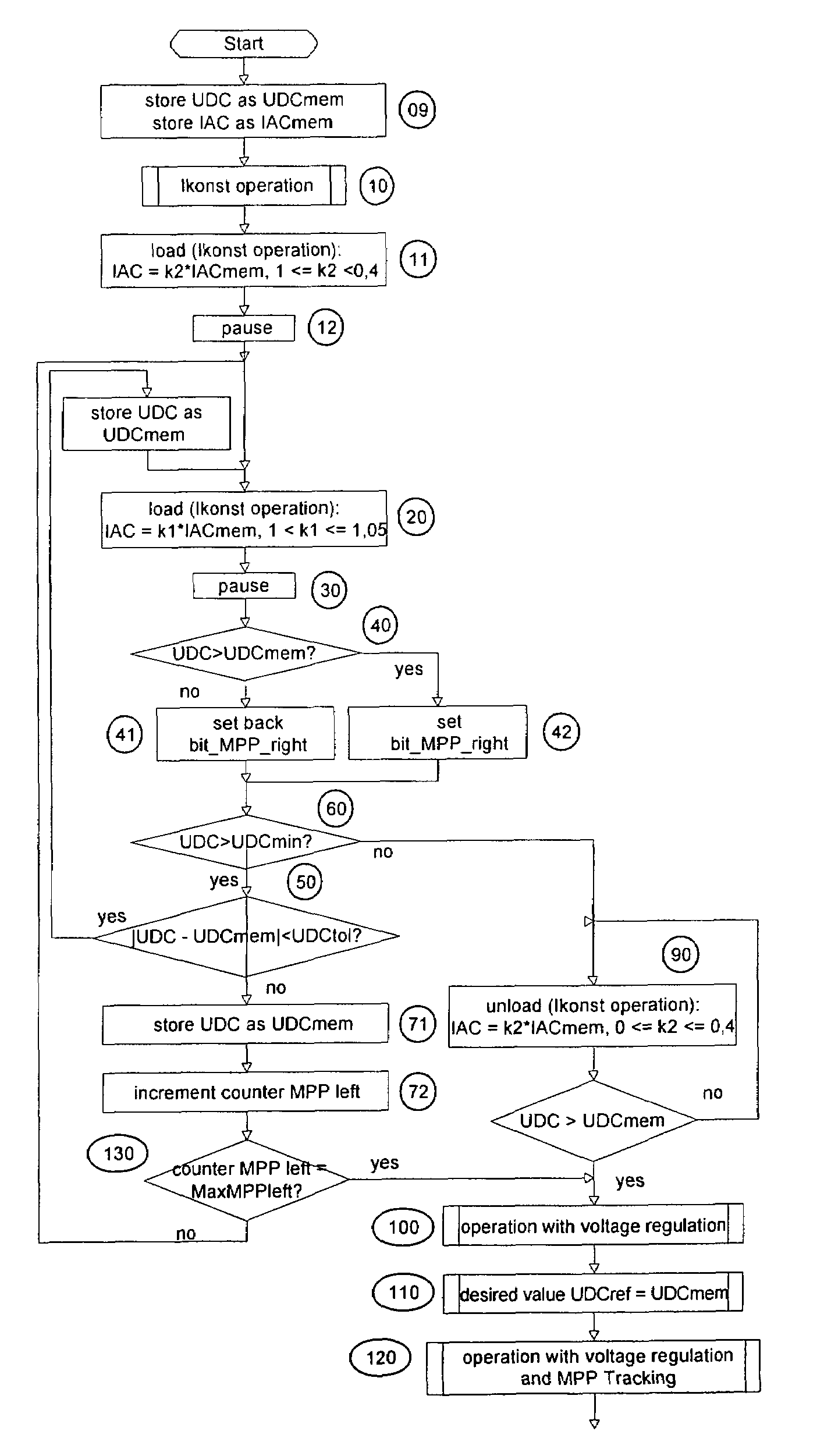
A method of finding a power maximum of a photovoltaic generator using an MPP regulator of a photovoltaic current converter by means of which a maximum generator power is set at an operating point of the generator's characteristic curve is intended to supply improved efficiency when the generator is partially shadowed. This is achieved by switching the MPP regulator off in order to next load and / or unload the generator to allow a new operating point of the generator's characteristic curve to set and by next switching the MPP regulator on again.

Description

[0001]This application claims Priority from German Application No. 0 2005 032 864.4-32 filed on 14. Jul. 2005BACKGROUND OF THE INVENTION[0002]1. Field of the Invention[0003]The invention relates to a method of finding a maximum power point of a photovoltaic generator.[0004]Photovoltaic generators have characteristic power curves generally including a maximum power operating point. A certain generator current and a certain generator voltage are associated with this operating point.[0005]Methods are known, by which the generator load, e.g., the generator current, is set so that the photovoltaic generator is operated at maximum power.[0006]Such type methods are referred to as Maximum Power Point Tracking (MPPT).[0007]2. Description of the Prior Art[0008]A method presented in DE 199 04 561 C1 consists in utilizing an additional sensor that measures the incoming radiation and sets a maximum power through a characteristic curve measuring circuit and a microcomputer. If a shadow falls onto...

Claims


Application Information

Patent Timeline
Patent Type & Authority Patents(United States)
IPC IPC(8): G05F5/00
CPCG05F1/67Y02E10/58Y02E10/56Y10S323/906
Inventor BETTENWORT, GERDKUHNEL, CHRISTIANAREND, OLIVERLASCHINSKI, JOACHIM RALFLEONHARDT, GERALD ALEXANDERREICHENBACHER, WOLFGANG KURT
Owner SMA SOLAR TECH AG
Learn More