
Dual polarization interferometers for measuring opposite sides of a workpiece

a technology of optical interferometer and workpiece, which is applied in the direction of interferometer, measurement device, instruments, etc., to achieve the effect of accurate matching

Active Publication Date: 2008-12-30
MITUTOYO CORP
View PDF14 Cites 4 Cited by
  • Summary
  • Abstract
  • Description
  • Claims
  • Application Information

AI Technical Summary

Benefits of technology

The present invention provides an optical interferometer that can measure changes in the thickness of a workpiece by measuring the interference fringe generated by the reflected light from the workpiece and the reference light. The optical interferometer includes two optical interferometers, one on the front surface and one on the rear surface of the workpiece. The interference fringe generated by the reflected light from the workpiece is captured by both interferometers, and the change in thickness of the workpiece can be obtained by matching coaxial points on the data captured by the two interferometers. The technical effect of the invention is to provide a more accurate and reliable method for measuring changes in the thickness of a workpiece.

Problems solved by technology

Firstly, light emitted from the light emitting section is incident on the polarization separator.

Method used


Image

  • Dual polarization interferometers for measuring opposite sides of a workpiece
  • Dual polarization interferometers for measuring opposite sides of a workpiece
  • Dual polarization interferometers for measuring opposite sides of a workpiece

Examples


first modification

[0115]In the first embodiment, the interference fringe sensor is provided with the polarizer for causing interference between the P wave and the S wave and the CCD camera for capturing the interference fringe. However, the interference fringe sensor may be a phase shift interference fringe sensor that simultaneously acquires phase interference fringes different from each other may be provided.

[0116]As the phase shift interference fringe sensor, an arrangement shown in FIG. 4 can be exemplified.

[0117]In FIG. 4, a phase shift interference fringe sensor 400 includes a quarter wavelength plate 410, a complex polarizer 420 and a complex CCD camera 430 as a capturing section.

[0118]The quarter-wavelength plate 410 changes the reference light of the S wave that is incident on the phase shift interference fringe sensor into circular polarized light. The quarter wavelength plate 410 also changes the object light of the P wave that is incident on the phase shift interference fringe sensor into...

second modification

[0125]As the phase shift interference fringe sensor, an arrangement shown in FIG. 6 may be alternatively employed.

[0126]In FIG. 6, a phase shift interference fringe sensor 500 includes a quarter wavelength plate 510, an imaging lens 520, a no-interference light beam dividing prism 530, a first, second and third polarized plate 541, 542 and 543 and a first, second and third CCD camera 551, 552 and 553.

[0127]The no-interference light beam dividing prism 530 includes a first triangle prism 531, a second triangle prism 532 and a trapezoid prism 533 which are adhered to each other. The no-interference light beam dividing prism 530 divides no-interference light into three light beams.

[0128]Surfaces on which the prisms 531 to 533 are adhered to each other are semi-transmissive.

[0129]The first to third polarized plates 541 to 543 are inserted in optical paths of light beams emitted from the no-interference light beam dividing prism 530. Transmission axis angles of the first to third polariz...

third modification

[0132]As the phase shift interference fringe sensor, an arrangement shown in FIG. 7 may be alternatively employed.

[0133]In FIG. 7, a phase shift interference fringe sensor 600 includes a quarter wavelength plate 610, half mirrors 621, 622 each dividing a light beam into three, a reflection mirror 623, polarizers 631 to 633 disposed in optical paths and CCD cameras 641 to 643.

[0134]The reference light Lb and the object light La having polarization directions orthogonal to each other are transmitted through the quarter wavelength plate 610 as a no-interference light beam. The no-interference light beam is transmitted through the quarter wavelength plate 610, so that the object light La and the reference light Lb in the no-interference light beam which have vibration directions orthogonal to each other becomes circular polarized light having rotation directions opposite to each other.

[0135]The light transmitted through the quarter wavelength plate 610 is divided into three light beams ...


PUM


Abstract

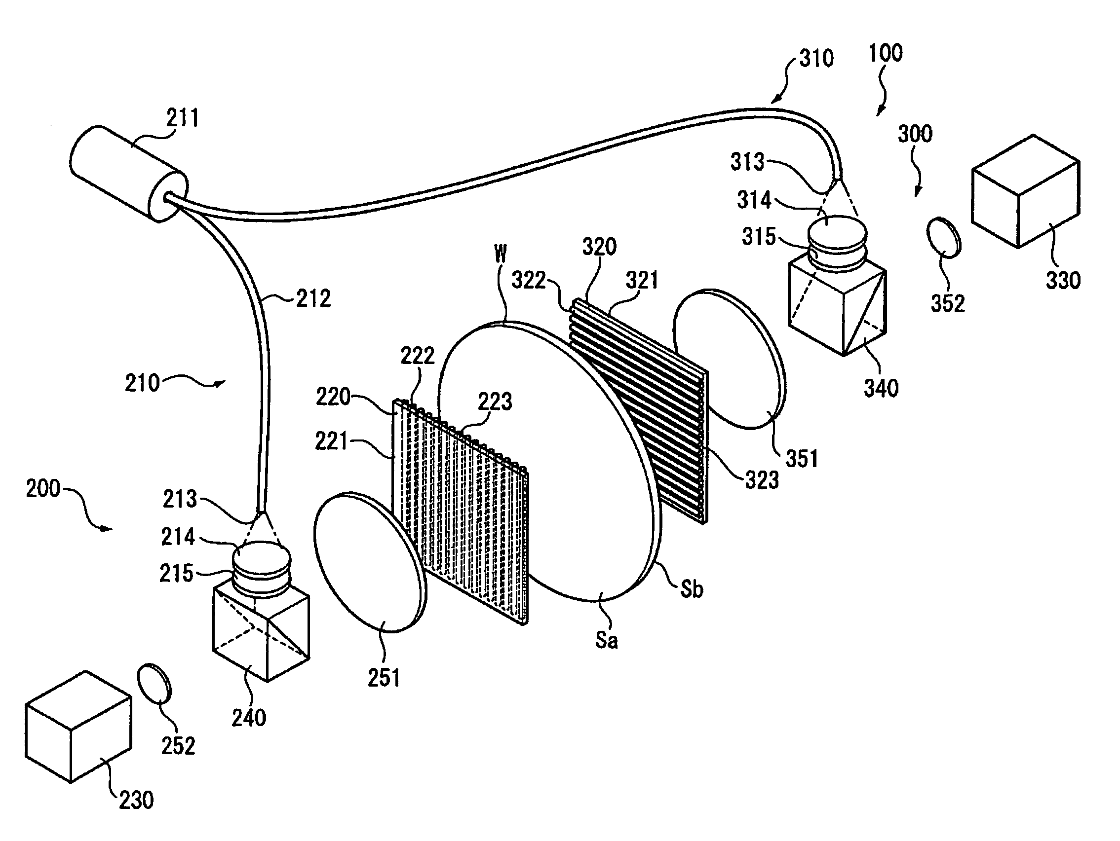
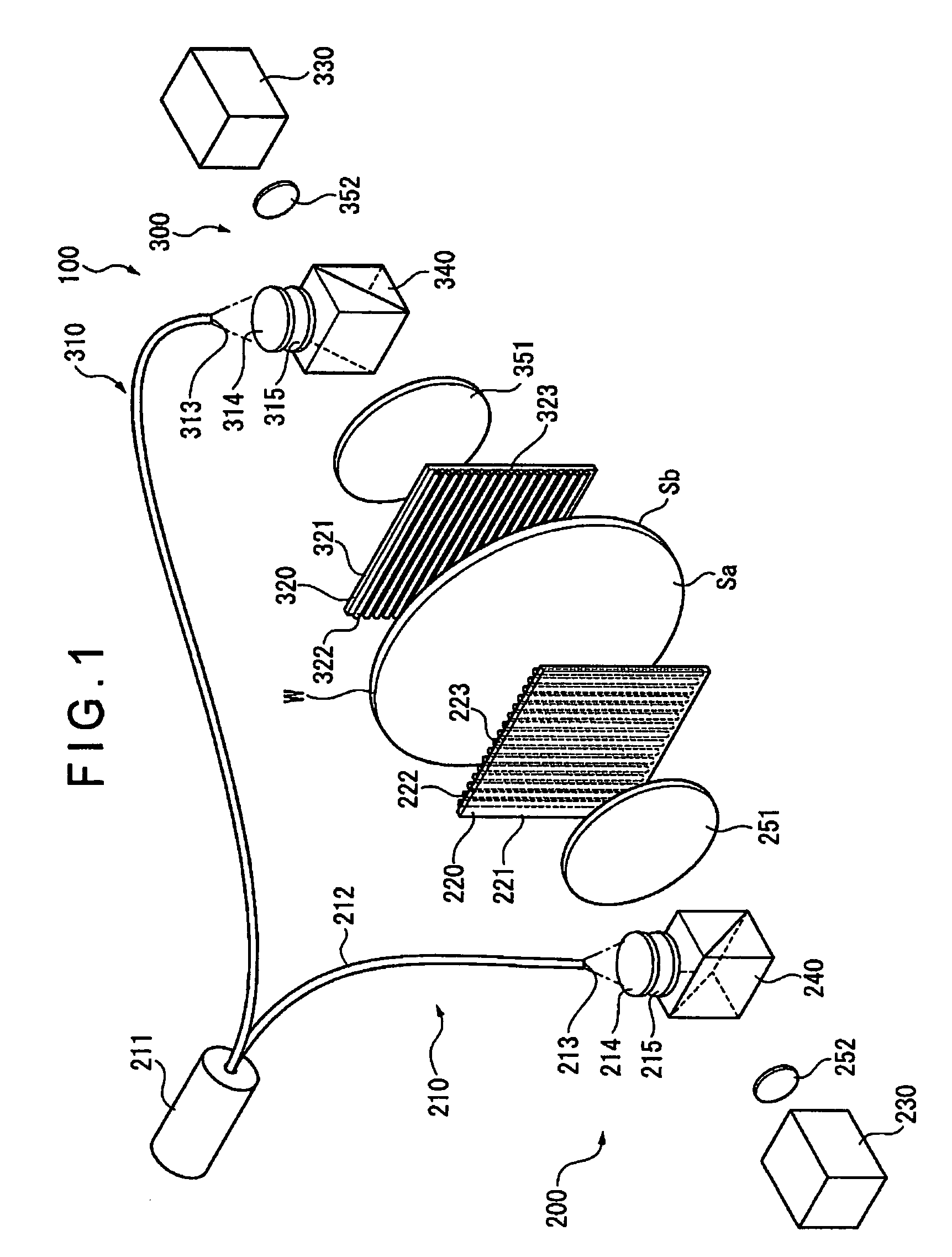
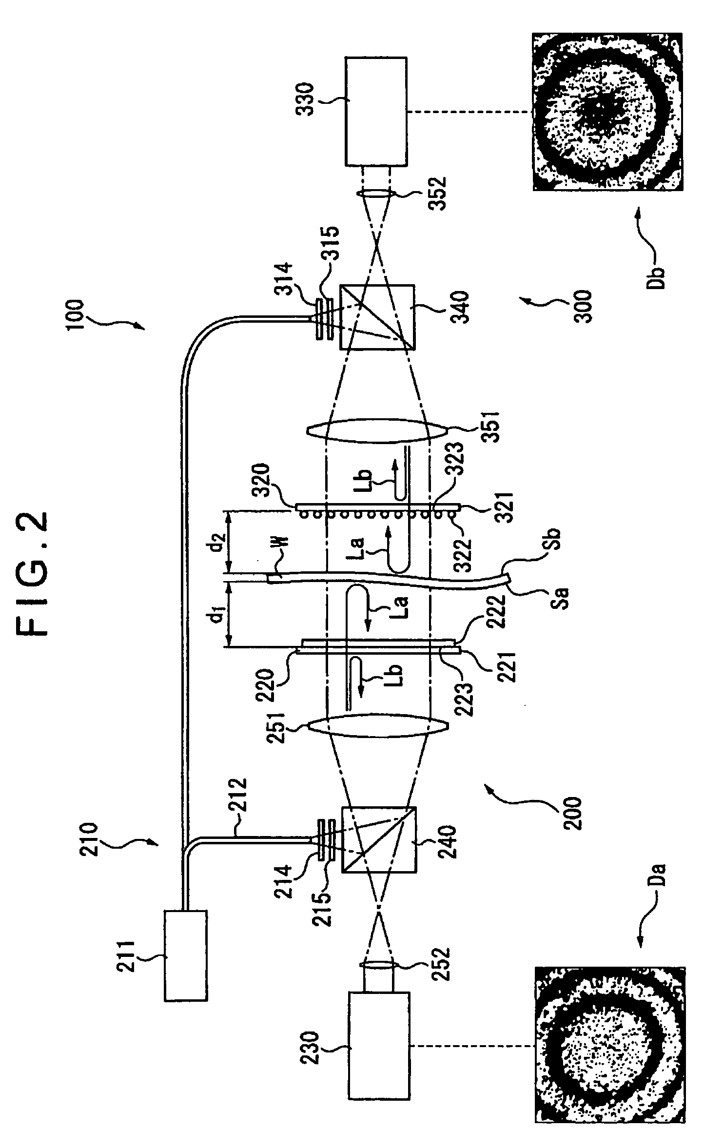
An optical interferometer (100) includes a first optical interferometer (200) disposed on a front surface side of a workpiece (W) and a second optical interferometer (300) disposed on a rear surface side of the workpiece (W). The first optical interferometer (200) and the second optical interferometer (300) each include a light emitting section (210, 310), a wire grid (220, 320) and an interference fringe sensor (230, 330). Wire alignment directions of the wire grid (220) of the first optical interferometer (200) and the wire grid (320) of the second optical interferometer (300) are orthogonal to each other. When no workpiece (W) is set, the wire grid (220) of the first optical interferometer (200) reflects light from the second optical interferometer (300) to generate object light and the wire grid (320) of the second optical interferometer (300) reflects light from the first optical interferometer (200) to generate object light.

Description

BACKGROUND OF THE INVENTION[0001]1. Field of the Invention[0002]The present invention relates to an optical interferometer. Specifically, the present invention relates to an optical interferometer that measures change in thickness of a to-be-measured object.[0003]2. Description of Related Art[0004]As a device for measuring an irregularity of a to-be-inspected surface, an optical interferometer has been known (for example, Document: JP-A-H08-35883).[0005]FIG. 8 shows a Michelson interferometer 10.[0006]In FIG. 8, light emitted from a light source 11 becomes a parallel light beam by a collimator lens system 12 and the parallel light is transmitted through a half mirror 13 and narrowed by a lens 14 disposed between the half mirror 13 and a workpiece W to be irradiated on the workpiece W. The light irradiated on the workpiece W is reflected by the workpiece W to be object light La. The object light La is reflected by the half mirror 13 to be incident on an interference fringe sensor. Be...

Claims


Application Information

Patent Timeline
Patent Type & Authority Patents(United States)
IPC IPC(8): G01B9/02G01B11/06
CPCG01B11/06G01B9/02028G01B9/02021G01B9/02057G01B9/02072G01B2290/70G01B2290/45G01B9/02027
Inventor JANSEN, MAARTEN
Owner MITUTOYO CORP
Learn More