Device for the low-deformation replaceable mounting of an optical element

a technology of replacing mounting and optical element, which is applied in the direction of mountings, microlithography exposure apparatuses, instruments, etc., can solve the problems of image defects of the respective optical element, unsuitable adjustment-free replacement, etc., and achieve the effect of simple replacementability and high reproducibility

Inactive Publication Date: 2008-12-30
CARL ZEISS SMT GMBH
View PDF15 Cites 5 Cited by
  • Summary
  • Abstract
  • Description
  • Claims
  • Application Information

AI Technical Summary

Benefits of technology

[0009]The present invention is based on the object of providing a device for the low-deformation mounting of an optical element in a mount of the type mentioned at the beginning which solves the disadvantages of the prior art and, if required, provides simple replaceability of an optical element, if possible without an additional mounting process, with high reproducibility by means of sufficient deformation decoupling.

Problems solved by technology

However, the mount described there can be set to the required lateral position only by means of an adjustment process and is accordingly not suitable for adjustment-free replacement.
Because of the use of more than three fixing screws for holding the mount, the mounting of the mount that is described is subject to disadvantageous single-wave and multi-wave deformation which results from this.
As a result of the adhesive connection of the optical elements, stresses can occur, which can lead to image defects of the respective optical element.

Method used


Image

  • Device for the low-deformation replaceable mounting of an optical element
  • Device for the low-deformation replaceable mounting of an optical element
  • Device for the low-deformation replaceable mounting of an optical element

Examples


Embodiment Construction

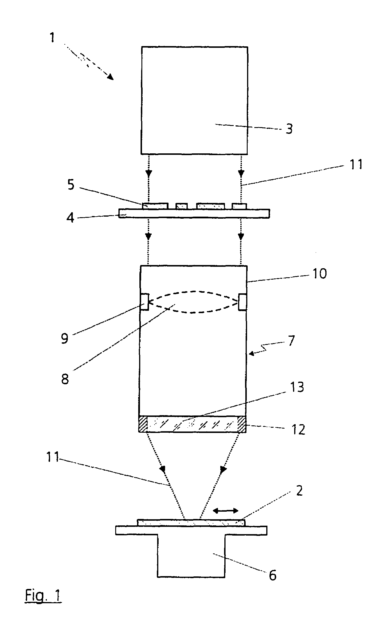
[0034]FIG. 1 illustrates a projection exposure system 1 for microlithography. This is used to expose structures on a substrate coated with photosensitive materials, which generally predominantly consists of silicon and is designated a wafer 2, for the production of semiconductor components, such as computer chips.

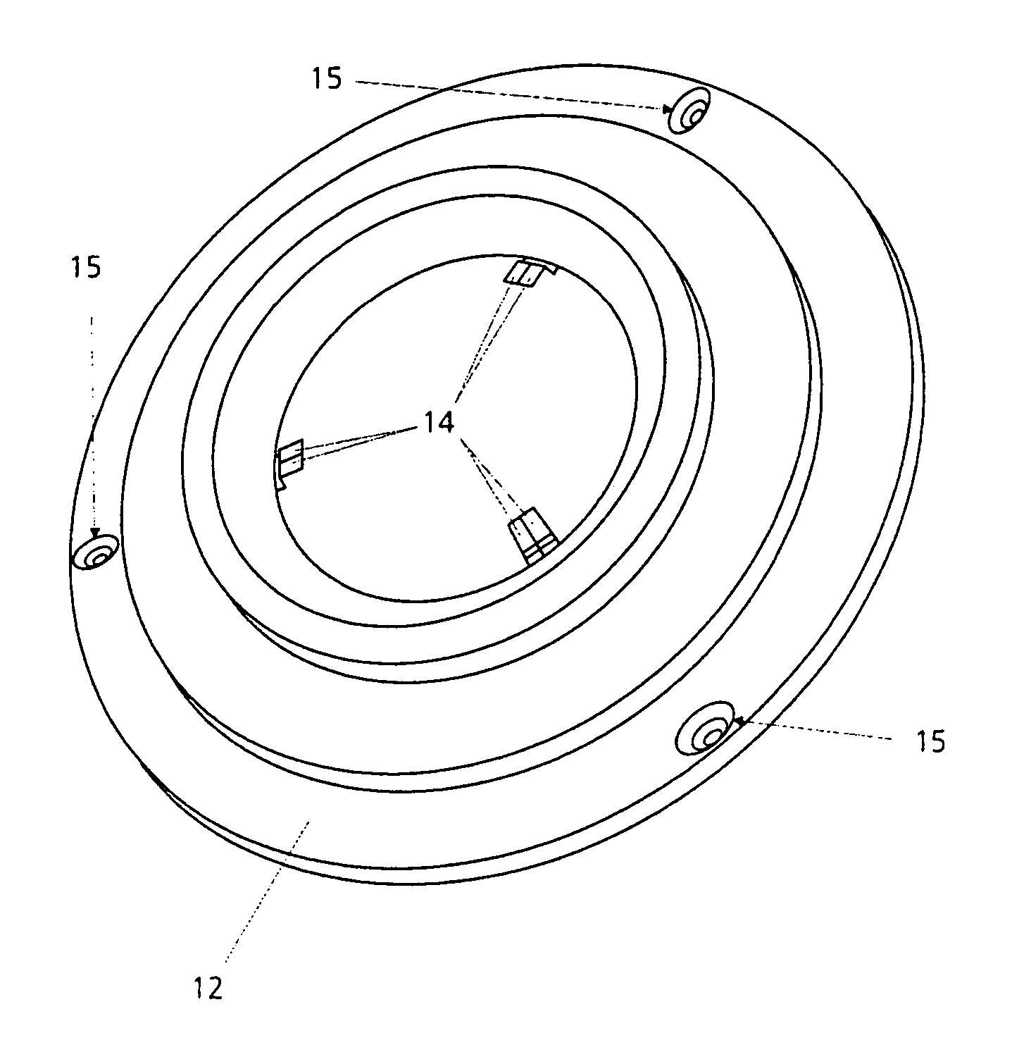
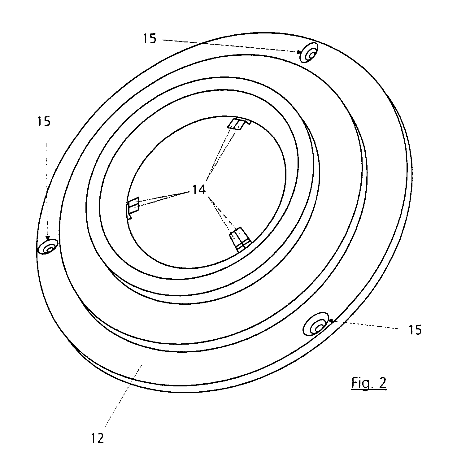
[0035]The projection exposure system 1 in this case substantially comprises an illuminating device 3, a device 4 for holding and exactly positioning a mask provided with a grid-like structure, what is known as a reticle 5, by which the subsequent structures on the wafer 2 are determined, a device 6 for holding, moving and exactly positioning just this wafer 2, and an imaging device, specifically a projection objective 7 having a plurality of optical elements, such as lenses 8, which are mounted via a mount 9 in an objective housing 10 of the projection objective 7.

[0036]The fundamental functional principle in this case provides for the structures introduced into the reticle...


PUM

PropertyMeasurementUnit
angleaaaaaaaaaa
thicknessaaaaaaaaaa
thicknessesaaaaaaaaaa

Abstract

The invention relates to a device for the low-deformation replaceable mounting of an optical element, in particular a closure plate of an objective of a projection exposure system for microlithography for the production of semiconductor components, in a mount (12). The optical element is connected to the mount (12) at least partly via an adhesive connection. This is located between the adjacent circumferential walls of mount (12) and optical element. The mount (12) is provided with at least three support feet (14) distributed over the circumference, by means of which the optical element is mounted laterally and axially. The mount (12) is connected to the housing of the objective in an at least approximately deformation-decoupled manner via three mount bearing points (15).

Description

PRIORITY CLAIM[0001]This is a Continuation-in-Part which claims priority from International Application No. PCT / EP2003 / 003110, entitled: Device for the Low-Deformation Replaceable Mounting of an Optical Element, filed Mar. 26, 2003, by Thomas Petasch, Dirk Schaffer, Andreas Wurmbrand, and Franz Sorg, the disclosure of which is incorporated herein by reference.BACKGROUND OF THE INVENTION[0002]1. Field of the Invention[0003]The invention relates to a device for the low-deformation replaceable mounting of an optical element, in particular a closure plate of an objective of a projection exposure system for microlithography for the production of semiconductor components, in a mount of the type defined in more detail in the preamble of claim 1.[0004]2. Description of the Related Art[0005]A generic device is described in EP 1 107 034 A2. According to that, it is already known to provide the mount with at least three support feet distributed around the circumference on which feet the optica...

Claims


Application Information

Patent Timeline
Patent Type & Authority Patents(United States)
IPC IPC(8): G02B7/02G02B7/00G03F7/20
CPCG02B7/00G02B7/025G02B7/026G03F7/70825
Inventor SORG, FRANZWURMBRAND, ANDREASPETASCH, THOMASSCHAFFER, DIRKWAHL, SIEGFRIED
Owner CARL ZEISS SMT GMBH
Why Eureka
Try Eureka