Electric compressor with inverter

a technology of electric compressor and inverter, which is applied in the direction of positive displacement liquid engine, piston pump, liquid fuel engine, etc., can solve the problems of increasing manufacturing cost, increasing cost after all, and electric compressor becoming large and heavy, so as to maintain the high cooling efficiency of the inverter

a technology of electric compressor and inverter, which is applied in the direction of positive displacement liquid engine, piston pump, liquid fuel engine, etc., can solve the problems of increasing manufacturing cost, increasing cost after all, and electric compressor becoming large and heavy, so as to maintain the high cooling efficiency of the inverter

US7473079B2Active Publication Date: 2009-01-06PANASONIC CORP

Image

  • Electric compressor with inverter
  • Electric compressor with inverter
  • Electric compressor with inverter

Examples


Embodiment Construction

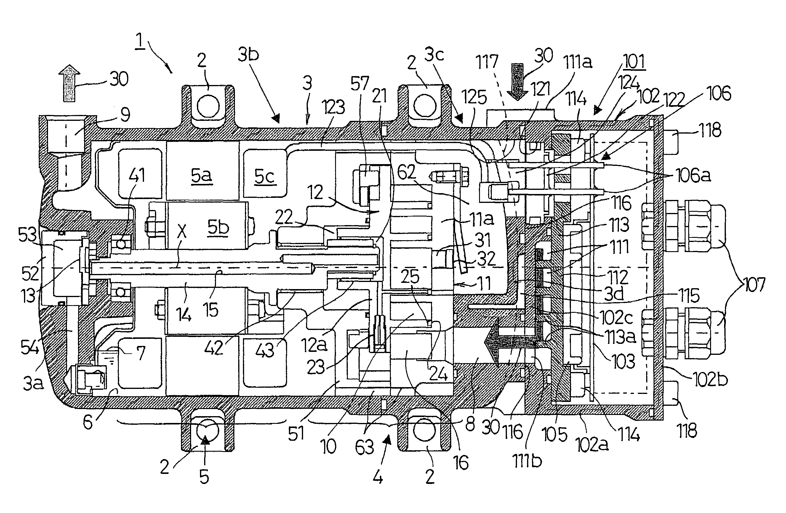
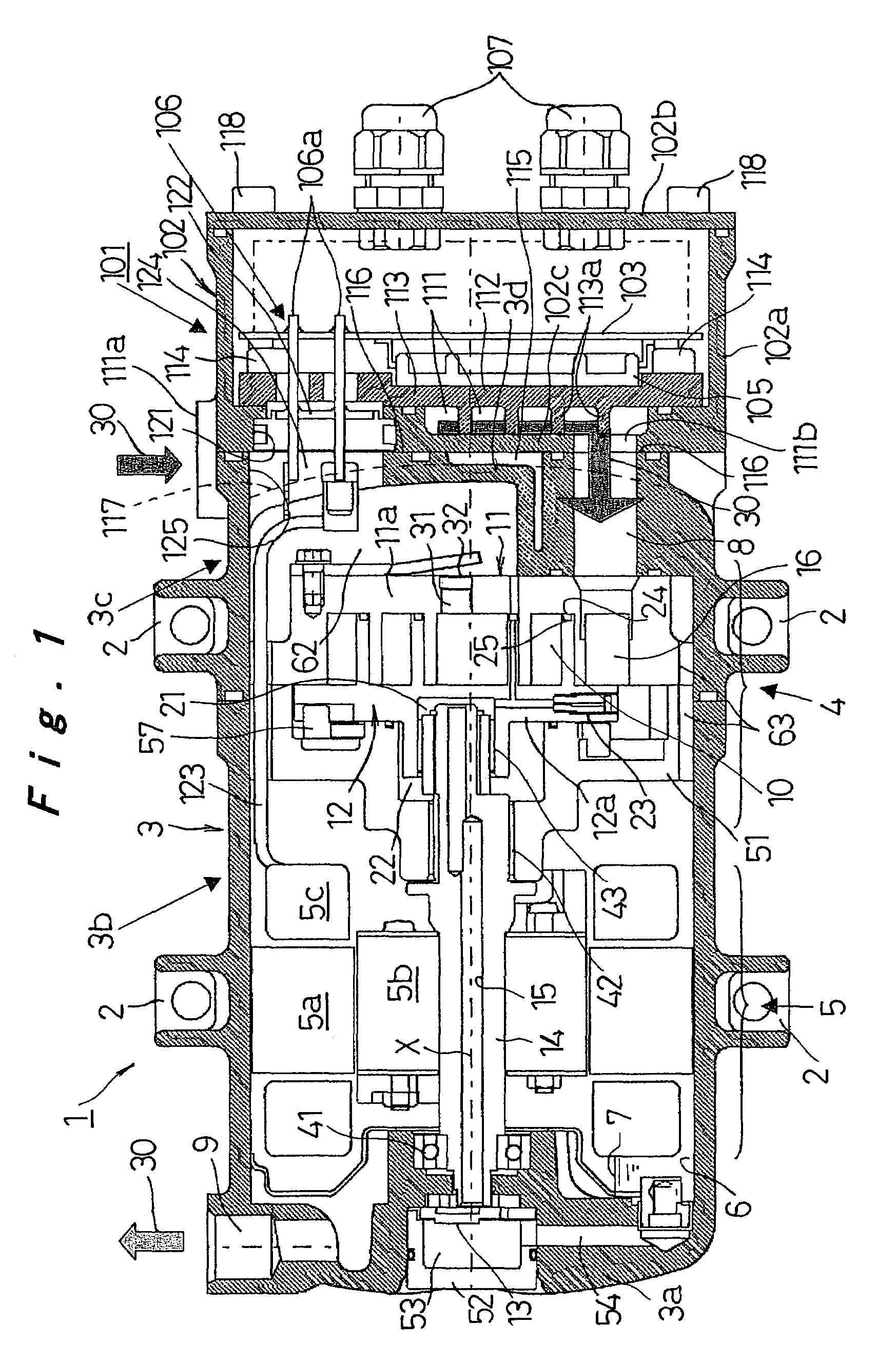
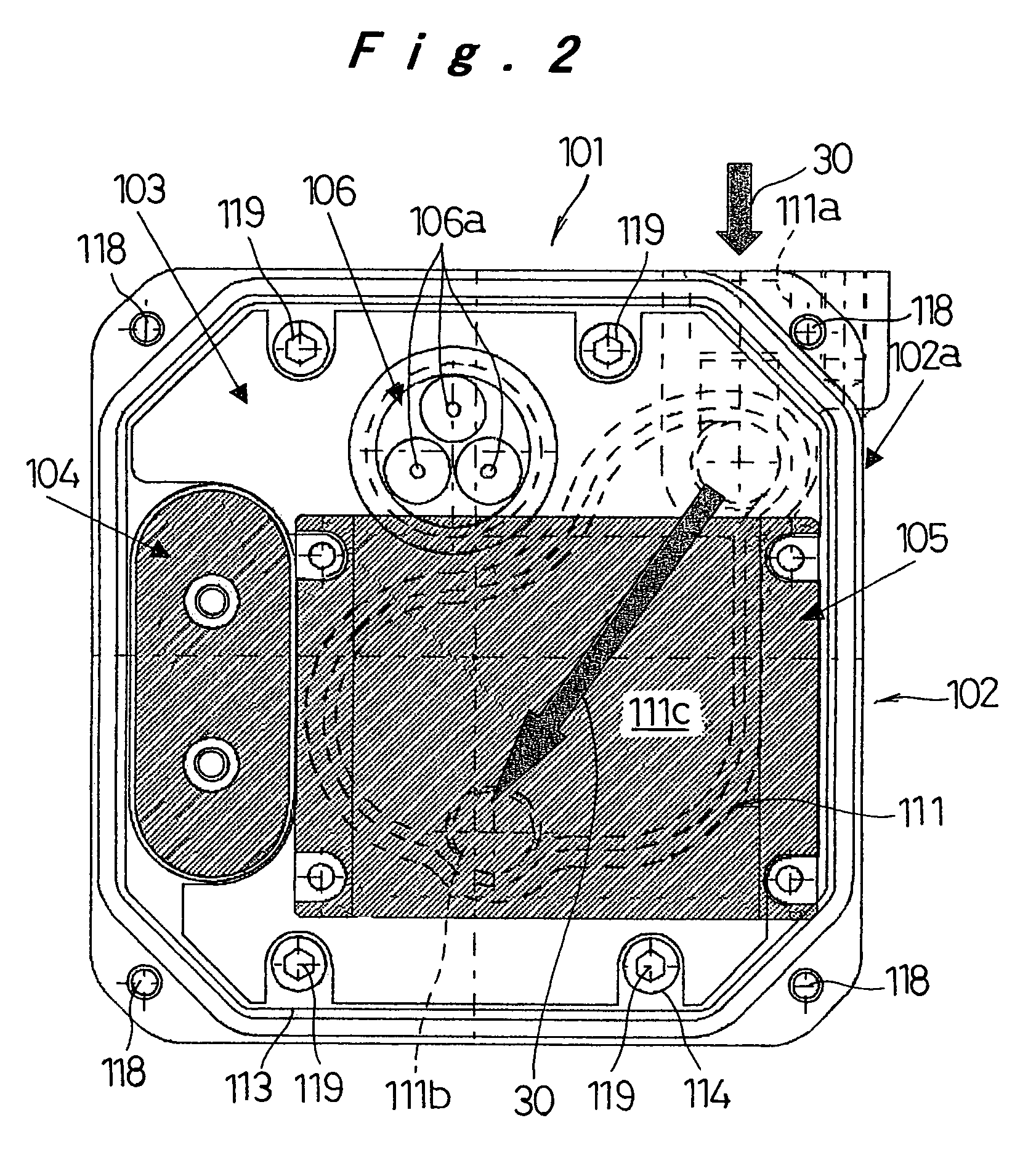
[0019]An embodiment of an electric compressor according to the present invention will be hereinafter described with reference to FIGS. 1 and 2. An electric compressor 1 according to this embodiment, as shown in FIG. 1, is installed horizontally by mounting legs 2 which are provided on the middle of a housing 3. The electric compressor 1 has the housing 3 which contains a compression mechanism 4, an electric motor 5 for driving the compression mechanism 4, and a reservoir 6 for retaining lubricant to lubricate sliding portions including the compression mechanism 4. An inverter 101 drives the electric motor 5. A gas refrigerant is used as a refrigerant, and lubricating oil 7 is used for lubricating the sliding portions and sealing the sliding portion of the compression mechanism 4. The lubricating oil 7 is compatible with the refrigerant. The present invention, however, does not limited to them, as long as an electric compressor includes a compression mechanism for sucking, compressin...


PUM


Abstract

In an electric compressor, an inverter case of an inverter is externally attached to an end wall of a housing in an axial direction on the side of a suction port to a compression mechanism. An intake passage for leading fluid returned from the outside into the suction port is provided in the inverter case. The intake passage has a thermal binding portion for thermally binding the intake passage to the inverter. According to the above structure, an exclusive part in the housing is eliminated even though the inverter is installed in the electric compressor, and the inverter is cooled efficiently.

Description

[0001]The present disclosure relates to subject matter contained in priority Japanese Patent Application No. 2002-355228, filed on Dec. 6, 2002, the contents of which is herein expressly incorporated by reference in its entirety.BACKGROUND OF THE INVENTION[0002]1. Field of the Invention[0003]The present invention relates to an electric compressor having a compression mechanism for sucking, compressing and discharging fluid, an electric motor for driving the compression mechanism, and a housing for containing the compression mechanism and the motor, in which the electric motor is driven by an inverter.[0004]2. Description of the Related Art[0005]In the electric compressor of this kind, an inverter, and a compression mechanism and an electric motor are installed separately from one another (refer to, for example, Japanese Patent Laid-Open Publication Nos. 2000-291557 (patent document 1), 2002-070743 (patent document 2), 2002-174178 (patent document 3), 2002-180984 (patent document 4),...

Claims


Application Information

Patent Timeline
06 Jan 2009
Publication
US7473079B2
IPC
F04B17/00; F04B35/04; F01C21/10; F04B39/06; F04B39/00; F04C18/02; F04C23/00; F04C29/00; F04C29/04
CPC
F01C21/10; F04C23/008; F04C29/0085; F04C29/045; F04C18/0215; F04C2240/30; F04C2240/808
Inventors
OGAWA, NOBUAKI; FUJIWARA, YUKIHIRO