Inversion device and method for converting direct-current voltage into alternating-current voltage and inverter

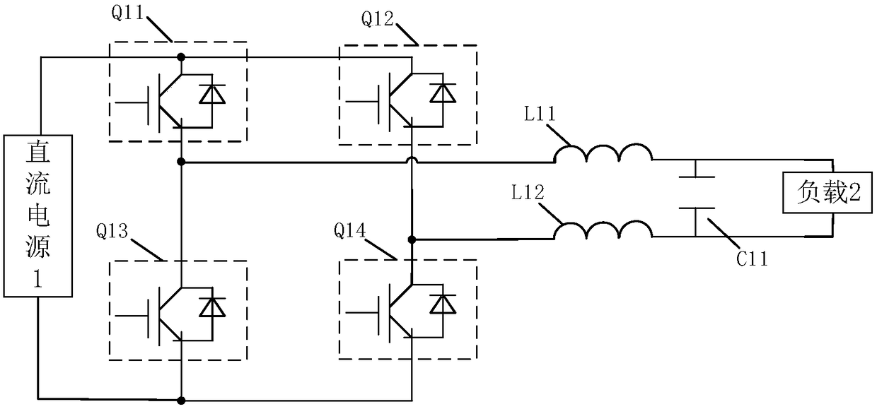
An inverter device and AC voltage technology, applied in the electronic field, can solve the problems of affecting the service life of the switching tube Q11 and the switching tube Q14, increasing the common mode voltage of the system, and the energy loss of the switching tube Q11 and the switching tube Q14.

Inactive Publication Date: 2019-02-12
BYD CO LTD
View PDF6 Cites 2 Cited by
  • Summary
  • Abstract
  • Description
  • Claims
  • Application Information

AI Technical Summary

Problems solved by technology

However, taking the bridge arm of the switching tube Q11 and the switching tube Q14 as an example, when the bridge arm of this group is turned off, since the current of the inductor L11 and the inductor L12 in the filter circuit will not change abruptly, and the inductor L11 and the inductor L12 also store Therefore, this part of energy will flow through the DC power supply circuit, increasing the common mode voltage of the system, resulting in an increase in the common mode leakage current, and at the same time, it is easy to generate oscillation during the freewheeling process, increasing the current ripple, causing the switching tube Increased voltage stress is not conducive to the improvement of inverter efficiency
Therefore, when this group of bridge arms is turned on next time, the excessive voltage stress will cause damage to the switch tube Q11 and the switch tube Q14, affect the service life of the switch tube Q11 and the switch tube Q14, and also cause the switch tube Q11 and the energy loss of the switching tube Q14 is too much, which will affect the inverter efficiency of the inverter; in addition, when each set of bridge arms is turned on, the inductor L11 and the inductor L12 will pass current and generate heat, which also affects the inverter inverter. variable efficiency

Method used


Image

  • Inversion device and method for converting direct-current voltage into alternating-current voltage and inverter
  • Inversion device and method for converting direct-current voltage into alternating-current voltage and inverter
  • Inversion device and method for converting direct-current voltage into alternating-current voltage and inverter

Examples


Embodiment Construction

[0038] Specific embodiments of the present disclosure will be described in detail below in conjunction with the accompanying drawings. It should be understood that the specific embodiments described here are only used to illustrate and explain the present disclosure, and are not intended to limit the present disclosure.

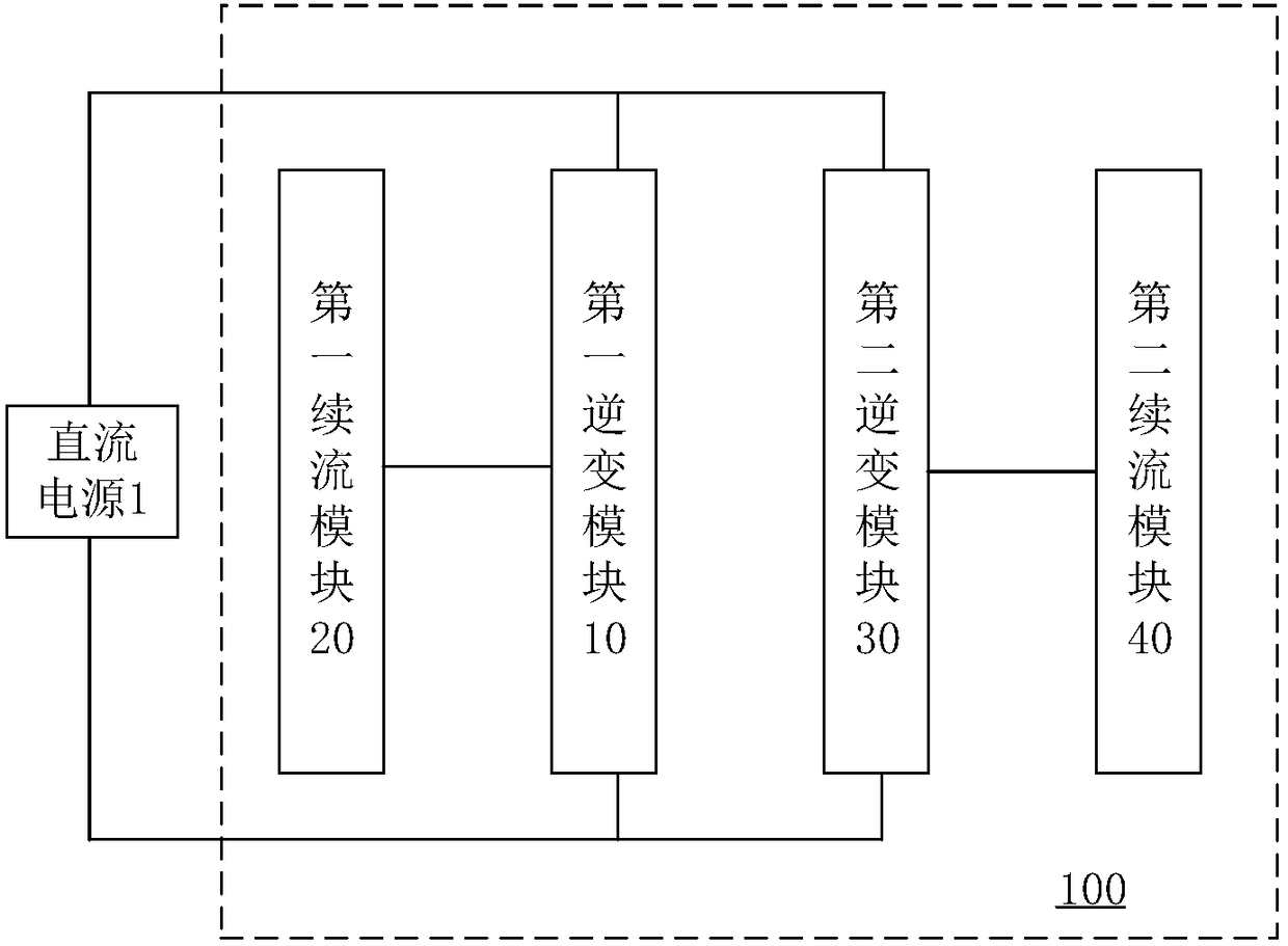
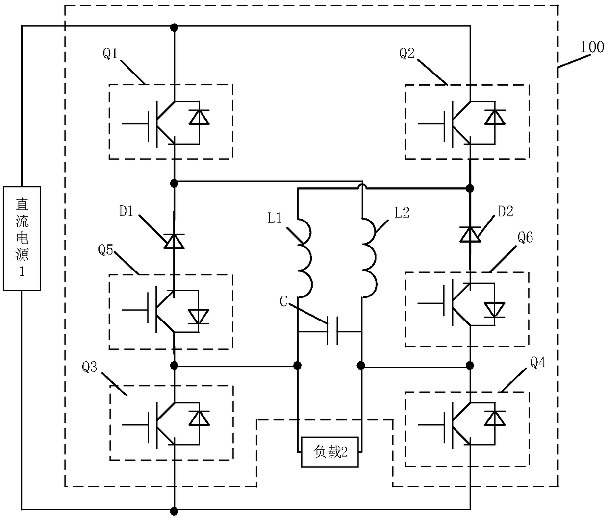
[0039] The present disclosure provides an inverter device 100 for converting DC voltage to AC voltage, such as figure 2 As shown, the inverter device 100 includes a first inverter module 10 , a first freewheeling module 20 , a second inverter module 30 and a second freewheeling module 40 .

[0040] The first inverter module 10 is used to invert the DC power supply 1 to obtain a positive half-wave signal of the AC power supply.

[0041] The first freewheeling module 20 is used to isolate the freewheeling current after the first inverter module 10 is disconnected from the DC power supply 1 .

[0042] When the first inverter module 10 is disconnected, the int...


PUM


Abstract

The invention relates to an inversion device and method for converting direct-current voltage into alternating-current voltage and an inverter and relates to the field of electronics. The inversion device comprises a first inversion module, a first follow current module, a second inversion module and a second follow current module, the first inversion module is used for inverting a direct-currentpower source to acquire a positive half-wave signal of an alternating-current power source, the first follow current module is used for inverting the direct-current power source into a negative half-wave signal of the alternating-current power source, the second follow current module is used for isolating follow current from the direct-current power source after the second inversion module is disconnected. The inversion device can lower common-mode leakage current, loop oscillation, ripple wave current and voltage stress of a switch tube in the inversion device, reduce energy loss of the switch tube and damage of the voltage stress to the switch tube, prolong service life of the switch tube, lower radiation of the switch tube and heat value and energy loss of an inductor and improve inversion efficiency.

Description

technical field [0001] The present disclosure relates to the field of electronics, and in particular, to an inverter device, method, and inverter for converting DC voltage to AC voltage. Background technique [0002] Common inverter circuits in inverters usually use such as figure 1 In the circuit shown, the switching tube Q11 and the switching tube Q14 are a group of bridge arms, which can get positive pulses when they are turned on, and the switching tube Q12 and the switching tube Q13 are a group of bridge arms, which can get negative pulses when they are turned on, and the two sets of switching tubes alternate When it is turned on, high-frequency chopping can be obtained, and then the required AC power can be obtained through the filter circuit composed of inductor L11, inductor L12 and capacitor C11. However, taking the bridge arm of the switching tube Q11 and the switching tube Q14 as an example, when the bridge arm of this group is turned off, since the current of th...

Claims


Application Information

Patent Timeline
Patent Type & Authority Applications(China)
IPC IPC(8): H02M7/497H02M7/515
CPCH02M7/497H02M7/515
Inventor 黄伟尹韶文尹雪芹
Owner BYD CO LTD
Why Eureka
Try Eureka