
Eureka
For R&D, Eureka makes reading and utilizing patents & technical documents easy.
Eureka AIR
Designed for self-driven R&D workflows. Generate viable solutions, solve complex R&D challenges, empower your innovation with AI.

Eureka Materials
Designed for material experts only. Revolutionize your material R&D, from search, analyze, to developing new materials.

TechResearch
Generate reliable direction feasibility study reports for your R&D in just a few steps.

TechSeek
Discover and master advanced knowledge NOW. Basics, ideas, possibilities, all at once.

TechMind
As an expert in R&D Theories, TechMind can generates customized viable solutions instantly.

TechRisk
Analyze your overall solution with one click, know your potential R&D risks in advance.

TechMonitor
Get weekly tech updates, stay abreast of the latest tech innovations and key insights.
Method for manufacturing a substrate for a flat panel display including forming grooves in a surface
- Summary
- Abstract
- Description
- Claims
- Application Information
AI Technical Summary
Benefits of technology
Problems solved by technology
Method used
Image

Examples
first embodiment
[0045]A method for manufacturing barrier ribs according to a first embodiment will now be described with reference to FIGS. 4A through 4E.
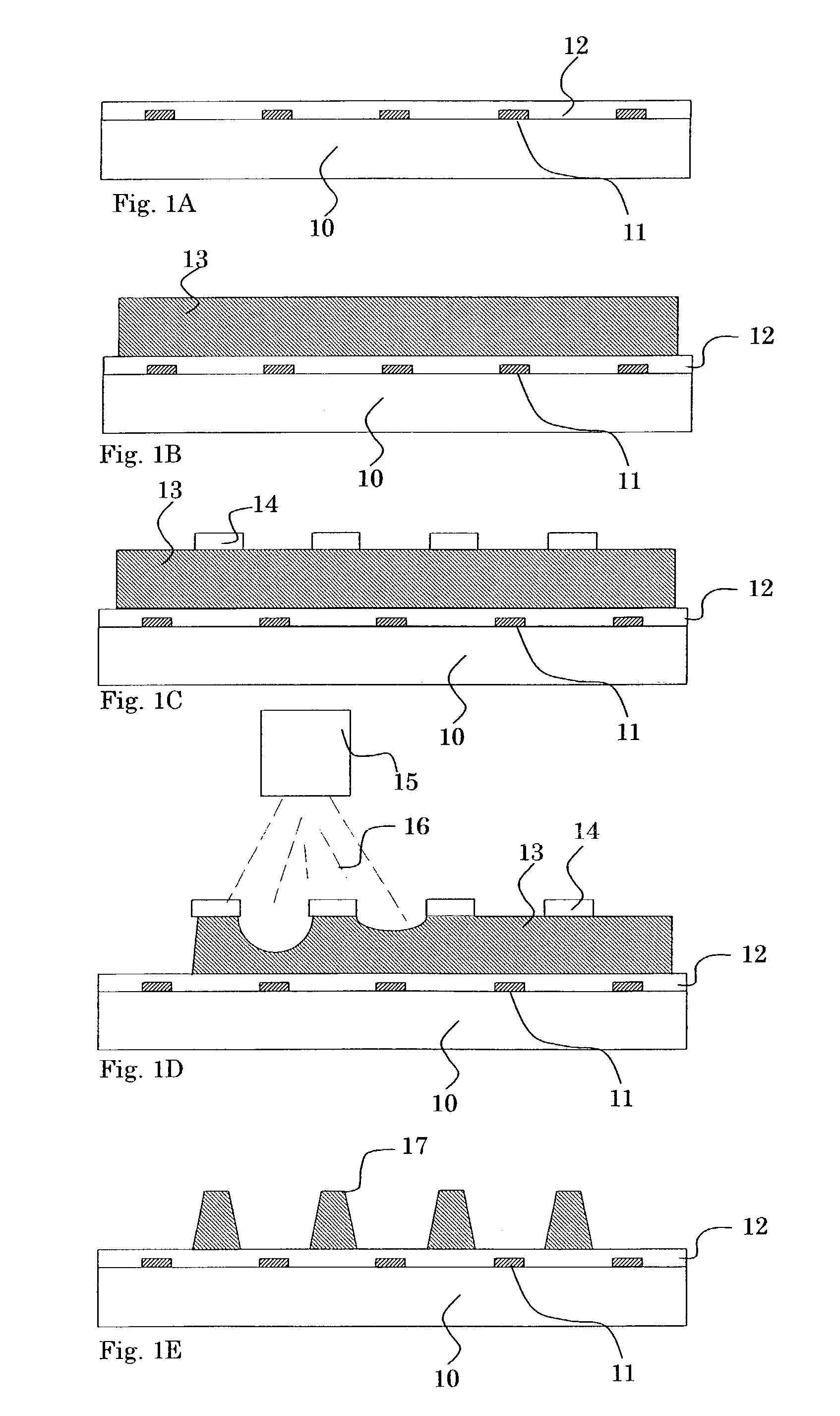
[0046]As shown in FIG. 4A, the dry resist film having sandblast resistance is joined to the bottom surface (tin-side surface) of a float glass substrate 30. The resulting dry resist film is developed by a photolithographic process to form resist pattern portions 31 such that the resist pattern portions 31 are disposed on corresponding regions for forming barrier ribs.
[0047]As shown in FIG. 4B, the bottom surface having the resist pattern portions 31 thereon is sandblasted with a sandblast gun 32 using an abrasive 33 comprising alumina or SiC particles having a diameter of about 10 to 20 μm to remove portions of the bottom surface, the portions not being covered with the corresponding resist pattern portions 31. Thereby, grooves 36 having a depth of about 150 to 200 μm are formed in the bottom surface.
[0048]As shown in FIG. 4C, the resist pattern p...
second embodiment
[0051]In the first embodiment, the address electrodes 35 are formed by the ink jet process or the dispensing process, as shown in FIG. 4C. However, in such a method, there is the following problem: when a conductive layer is-formed on the processed substrate surface by a sputtering process after the step shown in FIG. 4C and the conductive layer is etched by a photolithographic process to form address electrodes, an etchant enters spaces, caused by irregularities on the groove surface, between the address electrodes and the groove surface to cause the over-etching of the conductive layer, thereby causing no reproducibility of the address electrodes.
[0052]Thus, when the address electrodes are formed by a photolithographic process, at least the groove surface for forming the address electrodes must be smoothed to remove such irregularities. Since the irregularities are due to the uneven composition of the float glass substrate 30, the irregularities are caused even if the grooves are ...
third embodiment
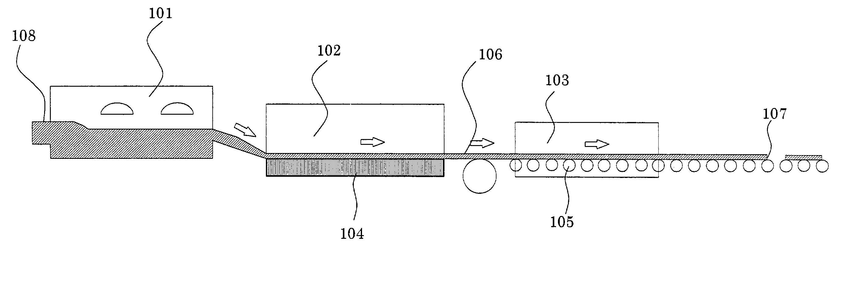
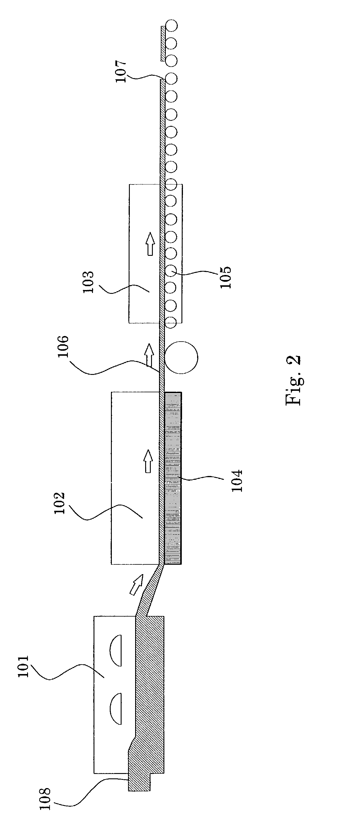
[0055]FIG. 7 is a schematic view showing an apparatus used for forming barrier ribs according to a third embodiment of the present invention. This apparatus includes a plurality of sandblast units. A float glass substrate 50 is supplied to an inlet port 54, wherein the float glass substrate 50 has resist pattern portions that are formed in the same manner as that shown in FIG. 4A, have sandblast resistance, and lie on the bottom surface (tin-side surface). The float glass substrate 50 then enters a sandblasting chamber 55, in which the bottom surface is sandblasted using #600 alumina particles, supplied from a first abrasive tank 51, having an average diameter of 20 μm. Thereby, grooves having a predetermined depth are formed in the bottom surface. The particles supplied from the first abrasive tank 51 are not limited to particles comprising alumina and may comprise SiC.
[0056]The resulting float glass substrate 50 is then sent to a first smoothing chamber 56, in which the bottom sur...
PUM
 Abstract
Description
Claims
Application Information
 - R&D Engineer
- R&D Manager
- IP Professional
- Industry Leading Data Capabilities
- Powerful AI technology
- Patent DNA Extraction
Browse by: Latest US Patents, China's latest patents, Technical Efficacy Thesaurus, Application Domain, Technology Topic, Popular Technical Reports.
© 2024 PatSnap. All rights reserved.Legal|Privacy policy|Modern Slavery Act Transparency Statement|Sitemap|About US| Contact US: help@patsnap.com