Materials system for low cost, non wire-wound, miniature, multilayer magnetic circuit components

a technology of magnetic circuit components and materials, applied in the direction of magnetic materials, magnetic bodies, inductances, etc., can solve the problems of inability to automate the coil winding process for such very small components, inability to meet current trend of increased functionality, and inability to manufacture such very small components. , to achieve the effect of enhancing the magnetic coupling coefficient, and enhancing the dielectric characteristics of interes

Inactive Publication Date: 2005-07-05
FERRO CORP
View PDF7 Cites 51 Cited by
  • Summary
  • Abstract
  • Description
  • Claims
  • Application Information

AI Technical Summary

Benefits of technology

[0021]The thick film dielectric of this invention is compatible with the ferrite and the thick film conductors of this invention and can be cofired with these materials. The magnetic permeability of this dielectric is less than that of the ferrite used in this invention. The dielectric is screen-printed as a protective film on top of the buried silver conductor. The presence of this dielectric helps in redirecting the magnetic flux around the buried silver induction coil there by enhancing the magnetic coupling coefficient for the miniature multilayer magnetic component. The dielectric film also acts as an insulator between adjacent buried silver conductor lines there by enhancing the dielectric characteristics of interest in applications of multilayer magnetic components.
[0022]In the preferred embodiment of this invention factors that enhance the dielectric characteristics such as breakdown voltage, insulation resistance and surge resistance are: use of Bi2O3 as a sintering aid in the ferrite, higher peak firing temperature of the multilayer package, reduced concentration of solids in the thick film buried silver conductor paste, presence of a grain growth inhibitor in the thick film buried silver conductor paste and, thickness of the dielectric film.

Problems solved by technology

Unfortunately this simple design of the traditional miniature wire-wound magnetic components is not conducive towards current trend of increased functionality and integration in electronic design and manufacturing of the circuit boards so as to reduce cost, size and, weight of the device.
Automation of the coil winding process is not feasible for such very small sized components.
Hence manufacturing of such very small sized components is costly due to the use of a labor-intensive manual wire-winding process.
By design, these miniature magnetic circuit components have following two shortcomings: (1) too large a form factor (height in relation to base of a component mounted on the circuit board) compared to that of the chip scale components needed for size and weight reduction of electronic devices of today and tomorrow and (2) cannot be integrated into the typical multilayer microelectronic manufacturing process to design a multi-functional / increased functionality component with inductive as well as capacitive and / or resistive functions for potential lowering of cost, size and weight of the electronic device.
These multilayer transformers of earlier inventions used materials systems that were not necessarily optimized for such applications.
These shortcomings have contributed to the slow pace of commercialization of this multilayer technique towards miniaturization and replacement of conventional wire-wound magnetic components such as inductors and transformers.

Method used


Image

  • Materials system for low cost, non wire-wound, miniature, multilayer magnetic circuit components
  • Materials system for low cost, non wire-wound, miniature, multilayer magnetic circuit components
  • Materials system for low cost, non wire-wound, miniature, multilayer magnetic circuit components

Examples


example 1

Preparing a Component

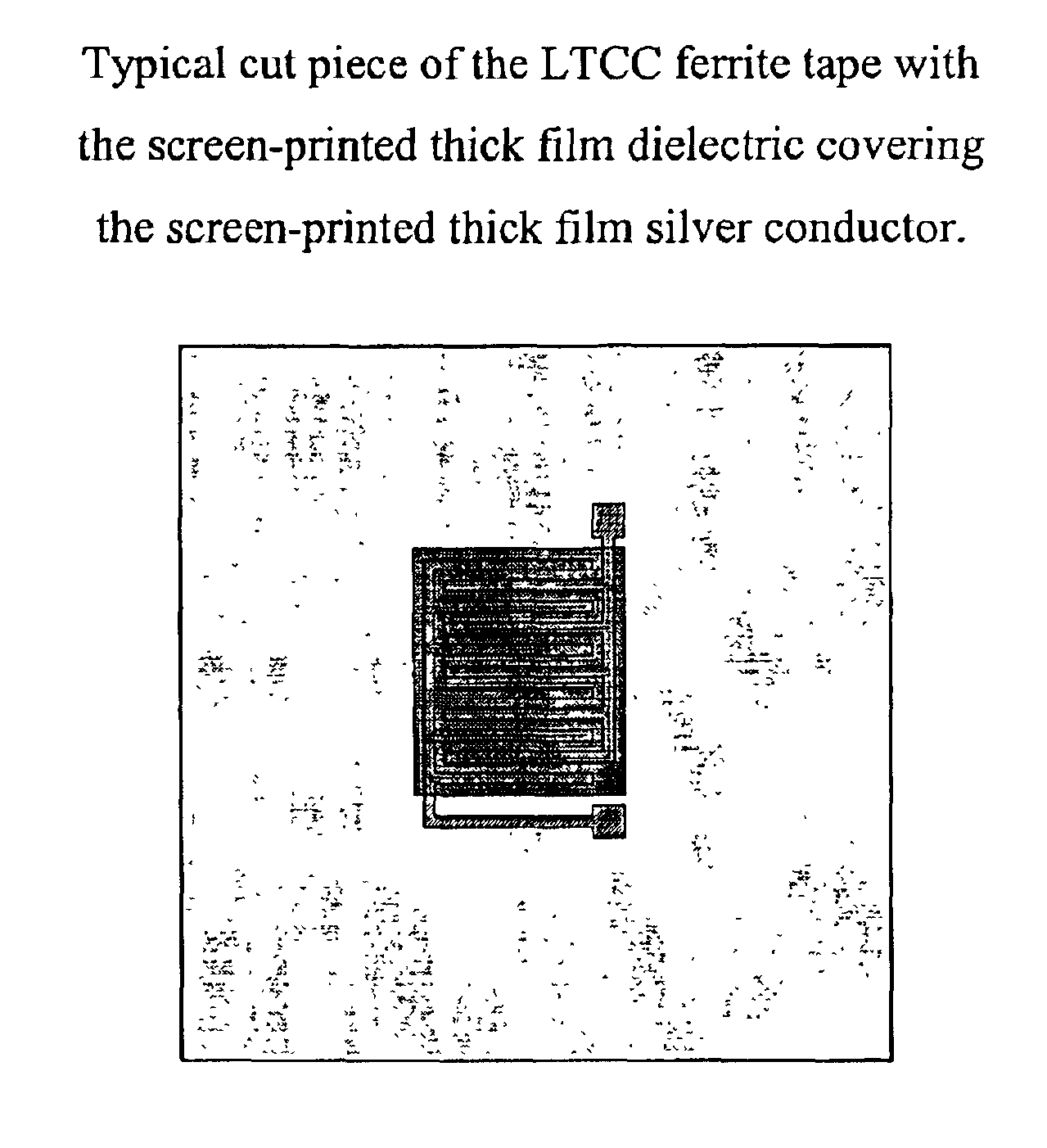
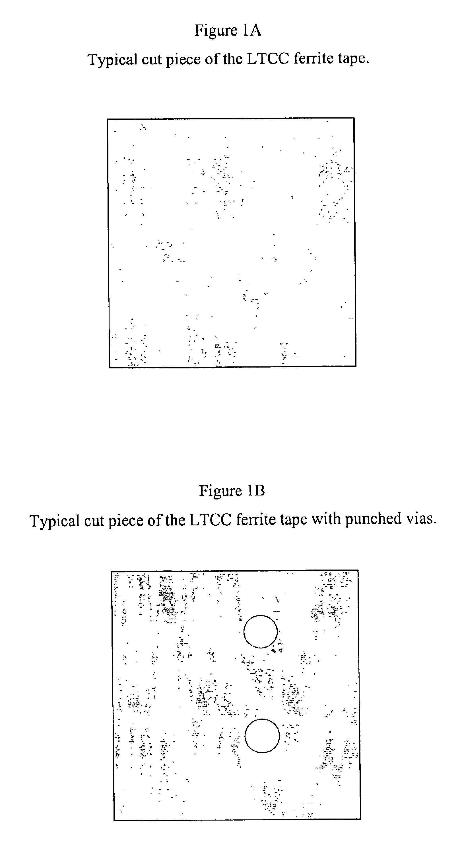
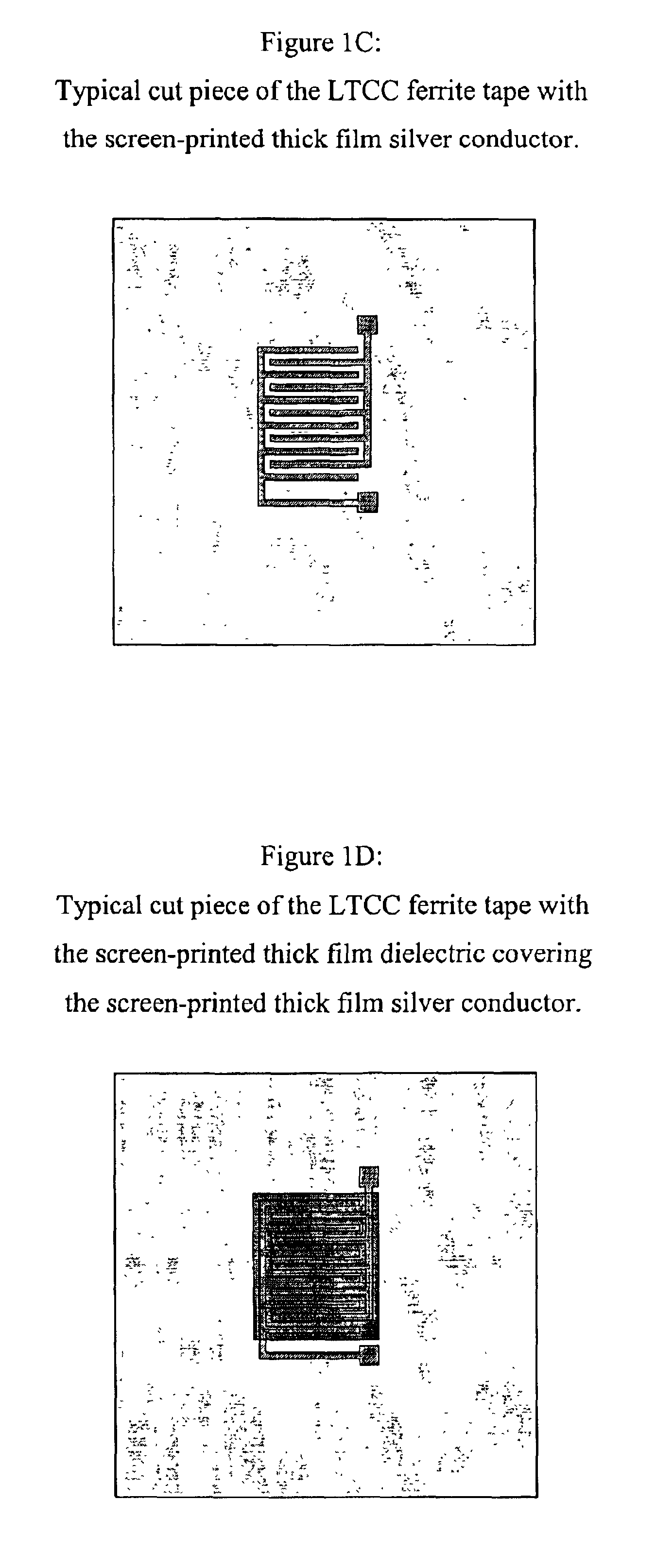
[0119]A non-wire wound, miniature, multilayer magnetic circuit component was constructed using the starting materials and techniques described herein. The component contained ferrite tape, thick film buried silver conductor, thick film via-fill silver conductor, thick film solderable top layer silver conductor and thick film dielectric. Following table lists the sequence of processing steps used and describes the layer-by-layer design of the multilayer component. (In an actual device, there may be circuits on several layers. The examples of devices disclosed below had circuits on only one layer or on none of the layers, since they were used for testing purposes only.)

[0120]

Multilayer partfor evaluatingthe effect ofMultilayer partthick filmfor testingdielectric onToroid fordielectricthe dielectrictestingproperties ofproperties ofProcessingmagneticthe ferritethe ferritestepspermeabilitytapetape1st step: cut10 pieces,10 pieces, each10 pieces, eachthe ferriteeach 1 ...

example 2

Firing the Component

[0121]A green multilayer package or magnetic component fabricated from the materials system of this invention can be fired using the following typical firing profile. Starting at room temperature, heat at a rate of 1° C. / min to 3° C. / min to the burn-off step temperature in the range 400° C. to 500° C. Hold at this burn-off step temperature for a duration of 15 minutes to 2 hours to facilitate optimum burn-off. Then continue heating at a rate faster than 4° C. / min to the peak firing temperature in the range of 850° C. to 950° C. Hold or soak at the peak firing temperature for duration of 15 minutes to 4 hours depending on the desired properties for the finished or fired multilayer package or magnetic component. The preferred firing profile for the materials system of this invention is as follows: Starting at room temperature, heat at a rate of 2° C. / min to the burn-off step temperature, 450° C. Hold at 450° C. for a duration of 2 hours. Then continue heating at a ...

example 3

Testing Magnetic Permeability of Toroid

[0123]In this embodiment the magnetic permeability, μm is measured using a toroid fabricated from a multilayer laminate of the LTCC ferrite tape. Ten layers of the LTCC ferrite tape are laminated and by means of a punch and a die set a green multilayer ferrite-ring with an inside diameter of 0.25 inch and an outside diameter of 0.625 inch is fabricated and fired to form the magnetic core for the toroid test part. The three dimensions, inside diameter, ID, outside diameter, OD and, thickness, t of the fired ring are recorded. Next, ten loops of an insulted wire are wound around the ring to form the toroid test part. An insulated wire, 26 AWG solid silver-plated OFHC copper 0.0055 KYNAR is used for the toroid windings and to facilitate electrical connection to the test equipment. The inductance, L of the toroid test part is measured with Wayne Kerr (West Sussex, UK) Precision Magnetics Analyzer, Model PMA 3260A, operating at 10 mA, 500 kHz. The m...


PUM

PropertyMeasurementUnit
weight %aaaaaaaaaa
weight %aaaaaaaaaa
softening pointaaaaaaaaaa

Abstract

This invention describes materials system and processing conditions for manufacturing magnetic circuit components such as induction coils and transformers that are non wire-wound, miniature in size and, have a low manufacturing cost. The materials system of this invention is comprised of: (1) Low Temperature Cofire Ceramic (LTCC) tapes or thick film pastes of ferromagnetic ceramics with a 20 to 750 range of magnetic permeability to form the magnetic core of the components, (2) Thick film buried silver conductor paste to form the planar induction coils on individual magnetic layers, (3) Thick film via-fill silver conductor paste to interconnect two or more of the planar induction coils through the thickness of the magnetic layers, (4) Thick film silver solderable top layer conductor paste compatible with the ferrite and, (5) Thick film dielectric paste with low magnetic permeability to redirect the magnetic flux for enhancing the magnetic coupling coefficient and to insulate the silver conductors for enhancing the dielectric breakdown voltage. The key characteristics of the materials system of this invention that facilitate manufacture of low cost non wire-wound, miniature magnetic circuit components are: (1) Mutual compatibility essential for either of the techniques, the cofire technique or the sequential technique, used for manufacturing multilayer hybrid microelectronic components, (2) Complementary thermo-physical properties such as shrinkage and thermal expansion coefficient essential for manufacturing flat multilayer magnetic components, (3) Magnetic components with magnetic coupling coefficients greater than 0.95 under optimal processing conditions and, (4) Magnetic components with dielectric breakdown voltage greater than 500V/mil under optimal processing conditions.

Description

CROSS REFERENCE TO RELATED APPLICATIONS[0001]This application claims priority from U.S. Provisional Patent Application Ser. No. 60 / 337,289, filed Nov. 8, 2001, which is incorporated in its entirety herein.STATEMENT REGARDING FEDERALLY SPONSORED RESEARCH OR DEVELOPMENT[0002]N / ABACKGROUND OF THE INVENTION[0003]Traditional miniature wire-wound magnetic circuit components are relatively simple in design compared to the miniature multilayer magnetic components manufactured using the materials system of this invention. Unfortunately this simple design of the traditional miniature wire-wound magnetic components is not conducive towards current trend of increased functionality and integration in electronic design and manufacturing of the circuit boards so as to reduce cost, size and, weight of the device. In the traditional miniature wire-wound magnetic component a very tiny wire is wound around a magnetic core to form the induction coil. Automation of the coil winding process is not feasib...

Claims


Application Information

Patent Timeline
Patent Type & Authority Patents(United States)
IPC IPC(8): H01F17/04C04B35/26H01F1/00H01F1/34H05K1/09H05K1/16H05K3/46
CPCC04B35/265C04B35/6264C04B35/6303H05K1/165C04B2235/3279C04B2235/3281C04B2235/3284C04B2235/3296C04B2235/3298C04B2235/3418C04B2235/365C04B2235/656C04B2235/6562H01F1/0027H01F1/344H05K1/095H05K3/4664H05K2201/086
Inventor WAHLERS, RICHARD L.HUANG, CORNELIUS Y. D.FEINGOLD, ALVIN H.HEINZ, MERRILL R.STEIN, MICHAEL ALAN
Owner FERRO CORP
Why Eureka
Try Eureka