Stent delivery system with securement and deployment accuracy

Active Publication Date: 2009-01-06
BOSTON SCI SCIMED INC
View PDF121 Cites 160 Cited by
  • Summary
  • Abstract
  • Description
  • Claims
  • Application Information

AI Technical Summary

Benefits of technology

[0014]The present invention is directed to several embodiments which seek to improve t

Problems solved by technology

As a result, in some instances, as the sheath is withdrawn from about the stent, the stent will tend to migrate or “jump” longitudinally relative to the stent mounting region of the catheter resulting in the imprecise delivery of the stent and/or d

Method used


Image

  • Stent delivery system with securement and deployment accuracy
  • Stent delivery system with securement and deployment accuracy
  • Stent delivery system with securement and deployment accuracy

Examples


Example

[0029]While this invention may be embodied in many different forms, there are described in detail herein specific preferred embodiments of the invention. This description is an exemplification of the principles of the invention and is not intended to limit the invention to the particular embodiments illustrated.

[0030]For the purposes of this disclosure, like reference numerals in the figures shall refer to like features unless otherwise indicated.

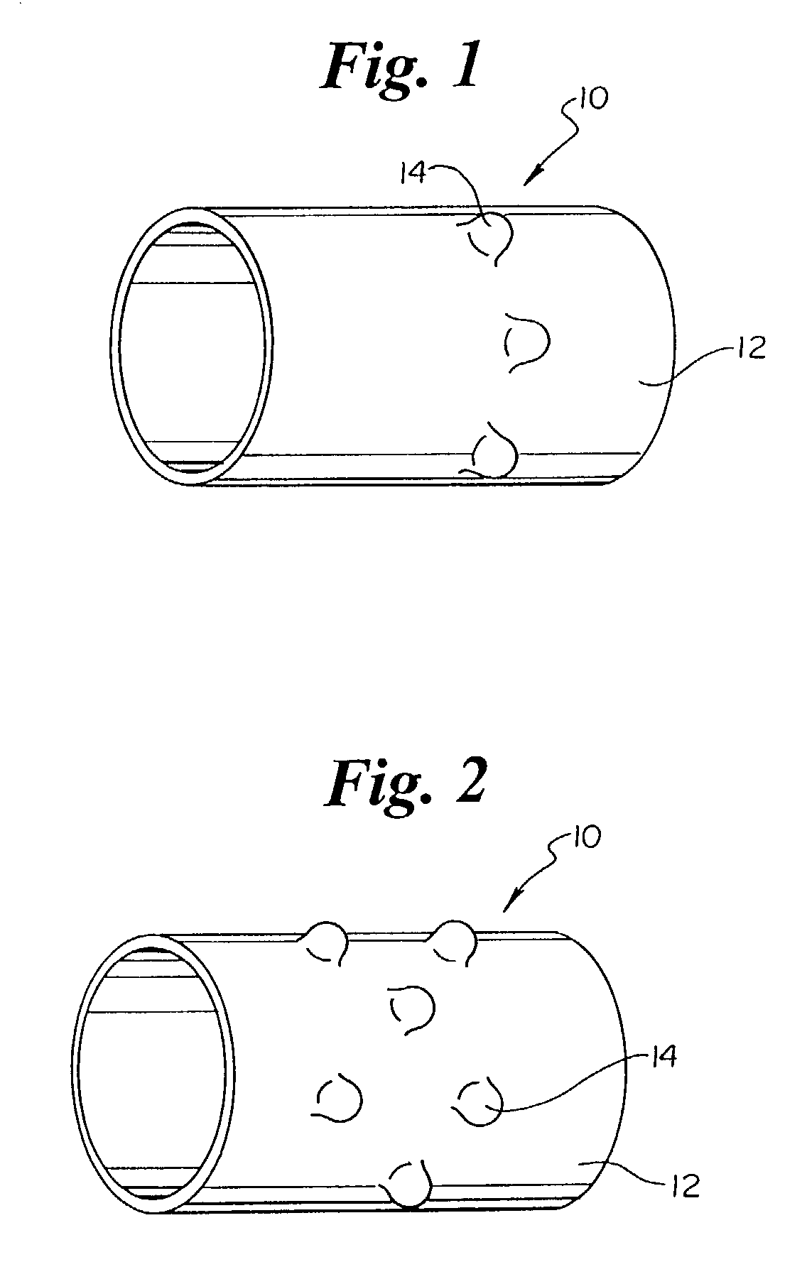
[0031]As mentioned above the present invention is embodied in a variety of forms. For example, in the embodiment shown in FIG. 1 the invention is embodied in a stent retaining band or collar, indicated generally at 10, which has an outer surface 12 comprising one or more protrusions 14. As illustrated by FIGS. 1 and 2 the protrusions 14 may have similar or differing dimensions and orientations relative to one another. In addition, the protrusions 14 may be arranged or positioned on the outer surface 12 by columns, rows, or any other pattern...


PUM


Abstract

A method and apparatus for reducing the longitudinal aspect of the catheter to stent force comprises at least one grip member for use with a stent delivery system. The grip engages a stent in the unexpanded state prior to delivery of the stent by retracting a stent retaining sheath. The grip comprises a body region having an outer diameter, a first end and a second end. The outer diameter of the first end is greater than the outer diameter of the second end. The grip is at least partially constructed from a polymeric material.

Description

CROSS-REFERENCE TO RELATED APPLICATIONS[0001]Not ApplicableSTATEMENT REGARDING FEDERALLY SPONSORED RESEARCH[0002]Not ApplicableBACKGROUND OF THE INVENTION[0003]The use of stents, and other implantable medical devices such as grafts, stent-grafts, vena cava filters, etc, hereinafter referred to cumulatively as stents, to maintain the patency of bodily lumens is well known.[0004]Stents are typically delivered via a catheter in an unexpanded configuration to a desired bodily location. Once at the desired bodily location, the stent is expanded and implanted in the bodily lumen.[0005]Typically, a stent will have an unexpanded (closed) diameter for placement and an expanded (opened) diameter after placement in the vessel or the duct. Some stents are self-expanding; some stents are expanded mechanically with radial outward force from within the stent, as by inflation of a balloon; and some stents, known as hybrid stents, have one or more characteristics common to both self-expanding and me...

Claims


Application Information

Patent Timeline
IPC IPC(8): A61F2/06A61F2/84
CPCA61F2/91A61F2/95A61F2002/9583A61F2002/9665
Inventor GUNDERSON, RICHARD
Owner BOSTON SCI SCIMED INC
Why Eureka
Try Eureka