Stacked coil array for magnetic resonance experiments

a magnetic resonance experiment and coil array technology, applied in the field of surface or volume array coil design for magnetic resonance imaging, can solve the problem of reducing the ability to unwrap under-encoded images collected using parallel imaging methods, and achieve the effect of improving g-factor and improving homogeneity and snr

Inactive Publication Date: 2009-01-06
NAT RES COUNCIL OF CANADA
View PDF15 Cites 29 Cited by
  • Summary
  • Abstract
  • Description
  • Claims
  • Application Information

AI Technical Summary

Benefits of technology

[0007]Rather than analyze the resultant signals from the loop and butterfly independently they are preferably combined into a single channel using an optimised combiner to increase the SNR at the depth of interest typically by 20%-30%. This is because the loop and butterfly are naturally isolated (decoupled) from each other so that no noise correlation exists. This gives rise to the well-known quadrature SNR gain. For that depth of interest, this technique is thought to maximize the SNR for a single channel.
[0010]The coil elements are thus arranged side by side along a longitudinal direction of the sample to be tested so as to define a line transverse to the longitudinal direction which is at the junction between the first and second coil elements. The junction at the transverse line can be provided by an overlap but is generally more preferably defined by a space between the combined array elements. Recent parallel MRI research into SENSE / SMASH optimized phased array designs has shown that the ability of an array coil to unwrap Nyquist folded MR images due to under-encoded k-space data is improved if neighbouring array elements are separated as opposed to overlapped. That is, there is a measure of image wrap artefact, the so called g-factor, that describes an array-coil's ability to unwrap under-encoded MR images. Generally, the g-factor is greater than 1 (the optimum value being 1 over the entire imaging plane). It has been found that the g-factor is reduced and closer to its optimum value of 1 for spaced array elements relative to overlapped array elements.
[0011]It is known that the SNR is disadvantageously reduced in between the array elements in the long dimension at the transverse line where the junction occurs. This is related to the SNR falloff of the individual array elements. Closing the gap between array elements or overlapping the array elements may reduce this fall-off but is clearly disadvantageous because it reduces the ability to unwrap under-encoded images collected using parallel imaging methods since it increases the G-factor.
[0014]An object of the present invention is to provide a new design for an array coil that improves the homogeneity and SNR at a desired depth of MRI and MRS while allowing an improvement in G-factor.
[0048]Thus the invention described and claimed herein proposes a new design of array coil that incorporates the traditional loop-butterfly array elements with stacked twisted loops and twisted butterfly elements. The goal is to allow separation of spine elements for improved parallel imaging capabilities such as SENSE and SMASH but to recover the SNR lost in between the elements and improve the g-factor of the total array with additional orthogonal array elements.
[0049]The twisted loop and twisted butterfly elements are not centered along the long axis with the loop-butterfly pair, but between the standard loop-butterfly array elements. The dimensions of the twisted array elements are chosen such that they are also naturally isolated from both the loop and butterfly, leading to SNR gain at the depth of interest. SNR gains are achieved at the depth of interest both between the loop-butterfly array elements as well as significant SNR benefits at depth at ends of the array along the long axis. Many higher order twisted array elements can be added that are also naturally decoupled from the loop-butterfly elements, but the SNR benefits of higher order twisted elements are not as significant at the depth of interest. With just adding one twisted loop and one twisted butterfly, long axis SNR gains at the depth of interest of 20%-40% can be achieved between loop-butterfly elements and approximately 35% at the ends of the array for improved z-axis coverage.

Problems solved by technology

Closing the gap between array elements or overlapping the array elements may reduce this fall-off but is clearly disadvantageous because it reduces the ability to unwrap under-encoded images collected using parallel imaging methods since it increases the G-factor.
The problem with this design is that naturally decoupled array elements were made by decreasing the sizes of the constituent parts.

Method used


Image

  • Stacked coil array for magnetic resonance experiments
  • Stacked coil array for magnetic resonance experiments
  • Stacked coil array for magnetic resonance experiments

Examples


third embodiment

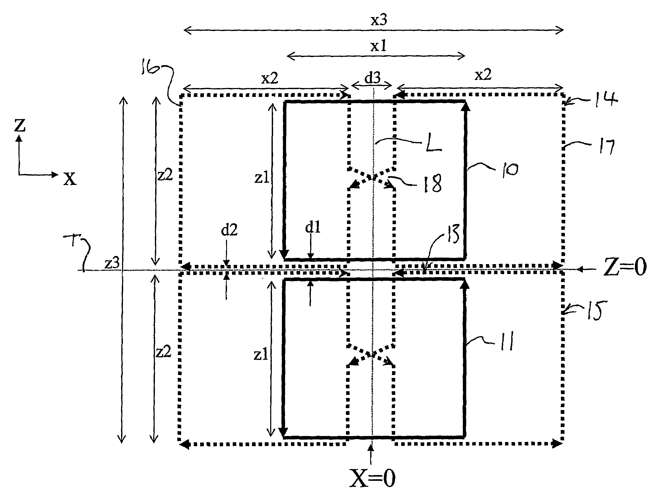
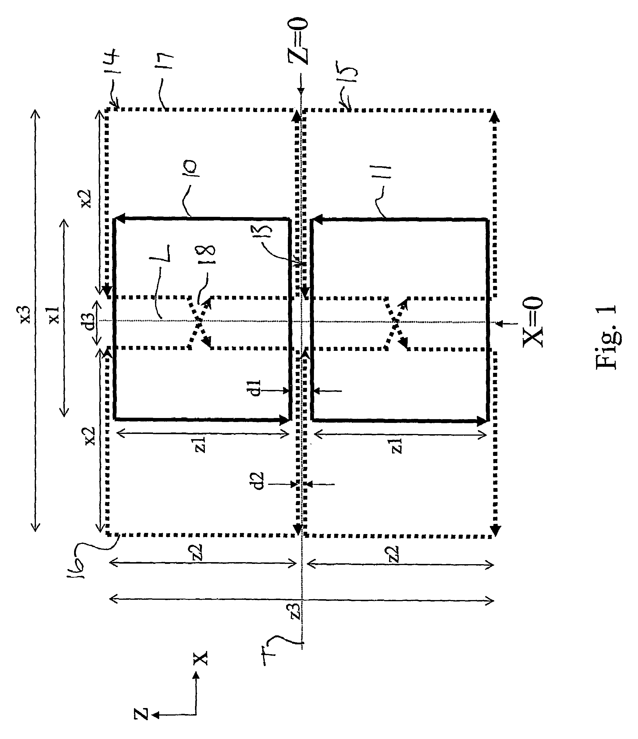
[0064]loops 10 and 11 can be used independently. The butterflies 14 and 15 can be used independently or in four coil elements can be used to provide the pair in the array either side of the transverse line T.

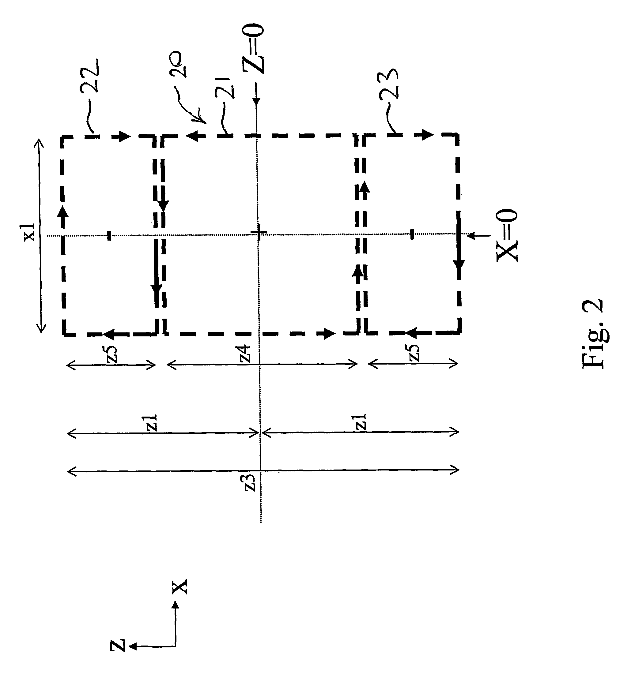
[0065]In FIG. 2 is shown a coil element construction which is called herein a “twisted loop”. The twisted loop 20 in FIG. 2 comprises a first coil 10 portion 21, a second coil portion 22 and a third coil portion 23. The coils portions 22 and 23 are twisted relative to the center coil portion 21 so that that current flows in opposite directions and so as to generate a field in opposite directions as indicated by the symbols + and −.

[0066]The dimensions of the twisted loop are arranged so that the sections 22 and 23 are generally of the order of one half of the dimension of the portion 21 in the longitudinal direction L. This ratio may vary between 40 percent and 60 percent. The total length of the three coil sections along the direction L is approximately equal to the sum of the ...

first embodiment

[0068]In the first embodiment, therefore, the twisted loop is utilized with the combination of FIG. 1 so that the twisted loop 20 is applied symmetrically along the longitudinal line L of the loops 10 and 11 with the center or first portion 21 bridging the gap 13.

second embodiment

[0069]In the second embodiment the twisted loop 20 is utilized with only the loops 10 and 11 without the butterflies 14 and 15.

[0070]In yet the further embodiment the twisted loop 20 can be used with only the butterflies 14 and 15 omitting the loops 10 and 11.

[0071]All of the coil elements are tuned to the same common frequency for simultaneous parallel reception of signals from a sample to be tested.

[0072]In FIG. 3 is shown a coil element construction which is called herein a “twisted butterfly”. This in effect comprises two twisted loops indicated at 20A and 20B which are arranged side by side about the longitudinal directed line L. The two twisted loops 20A and 20B are twisted about a central area 25 between the two central conductors. This provides the current path as shown by the arrows extending around the various coil elements and the field arrangements as indicated by the symbols + and −. Thus the two twisted loops 20A and 20B are symmetrical but inverted one relative to the...


PUM


Abstract

An array coil for sensing signals in magnetic resonance experiments incorporates the traditional loop-butterfly array elements at spaced positions along an axis of the sample with additional stacked twisted loops and / or twisted butterfly elements. The twisted loop and twisted butterfly elements are centered along between the standard loop-butterfly array elements. The twisted array elements are naturally isolated from both the loop and butterfly. Alternatively, for a two dimensional mesh array of loop elements, additional twisted loop array elements are added with both longitudinal and transverse orientations, again centered between loop elements. The goal is to allow separation of loop and / or butterfly elements of linear (Spine), 2D planar arrays (Cardiac) or cylindrical arrays of curved array elements (Head), for improved parallel MRI capabilities such as the SENSE or SMASH techniques, but to recover the SNR lost in between the elements and improve the g-factor of the total array with additional orthogonal array elements.

Description

[0001]This invention relates to surface or volume array coil designs for Magnetic Resonance Imaging (MRI) and Spectroscopy (MRS) using a plurality of coil elements which are tuned to a common frequency for simultaneous parallel reception of signals from a sample to be tested or alternatively in transmission for excitation of a sample to be tested.[0002]The coil arrays disclosed and claimed herein are primarily designed as sensing coils for detecting signals from the sample but can be used as field generating coils or as both sensing and generating coils as required. It will be appreciated that such coils which include de-coupled components are both de-coupled in respect of a field generated from an input signal and noise received in the signal from the sample and the description hereinafter may refer to either.[0003]Surface and volume coils are used for magnetic resonance experiments including both magnetic resonance imaging (MRI) and magnetic resonance spepctroscopy (MRS).[0004]Pre...

Claims


Application Information

Patent Timeline
Patent Type & Authority Patents(United States)
IPC IPC(8): G01V3/00G01R33/34G01R33/3415
CPCG01R33/3415
Inventor KING, SCOTT
Owner NAT RES COUNCIL OF CANADA
Why Eureka
Try Eureka